Engine device

a technology of engine and mounting mechanism, which is applied in the direction of machines/engines, transportation and packaging, and mounting of jet propulsion machines, etc., can solve the problems of inability to easily improve the mounting property of the engine to a vehicle body or a general versatility of the engine, and the inability to easily secure the attachment position of the support mechanism which is suitable for supporting the exhaust gas purification device, so as to facilitate lighten the oscillation of the engine and reduce the restriction of the vehicle body structur

Active Publication Date: 2017-07-20
YANMAR POWER TECHNOLOGY CO LTD
View PDF12 Cites 8 Cited by
  • Summary
  • Abstract
  • Description
  • Claims
  • Application Information

AI Technical Summary

Benefits of technology

[0018]According to the embodiment of the present invention, the exhaust gas purification device is provided with the DPF case which removes the particulate matters in the exhaust gas of the engine, the SCR case which removes the nitrogen oxides in the exhaust gas of the engine, and the urea mixing pipe which injects the urea water into the exhaust gas of the engine, the upper surface of the support base is provided with the DPF case mounting portion which mounts the DPF case, and the SCR case mounting portion which mounts the SCR case, the DPF case and the SCR case are arranged side by side in the upper surface side of the support base, and the upper surface of the SCR case mounting portion of the support base is formed lower than the upper surface of the DPF case mounting portion of the support base in the upper surface of the support base. As a result, it is possible to make the support position of the urea mixing pipe low by lowering the support position of the SCR case, in spite that it is possible to easily lighten the oscillation of the engine which is supported in an oscillation preventing manner to the vehicle body of the various vehicles, by lowering the support position of the exhaust gas purification device and setting the center of gravity of the engine to the low position. Therefore, it is possible to form a whole height of the engine low, it is possible to reduce the restriction of the vehicle body structure of the vehicle mounting the engine thereto, and it is possible to easily improve the mounting property of the engine to the vehicle body or the general versatility of the engine.
[0019]According to the embodiment of the present invention, the intake air manifold of the engine is provided with the exhaust gas recirculation device which supplies a part of the exhaust gas of the exhaust gas manifold, and the EGR cooler, the exhaust gas manifold is installed in the side surface of the cylinder head of the engine, the supercharger and the exhaust gas outlet pipe are arranged in close vicinity to the upper surface side of the exhaust gas manifold, and the EGR cooler is arranged in close vicinity to the lower surface side of the exhaust gas manifold. As a result, the exhaust gas purification device can be installed with low height to the upper surface side of the engine via the support base, an engine room of the vehicle mounting the engine thereto can be structured compactly, and it is possible to easily improve the mounting property of the engine to the vehicle body or the general versatility of the engine, in spite that the supercharger and the EGR cooler can be supported compactly to the engine side surface to which the exhaust gas manifold is installed.
[0020]According to the embodiment of the present invention, in the engine device having the exhaust gas purification device which removes the particulate matters in the exhaust gas of the engine or the nitrogen oxides in the exhaust gas of the engine, the exhaust gas purification device is firmly fixed to the support base, the support base is mounted to the engine via the support leg body, and the engine suspension member for attaching and detaching the engine is firmly fixed to the support leg body. As a result, the attachment position of the support leg body or the attachment position of the engine suspension member is not restricted each other, and it is possible to easily secure the attachment position of the support leg body which is suitable for supporting the exhaust gas purification device, or the attachment position of the engine suspension member which is suitable for moving the engine in a suspended state. It is possible to easily select the attachment layout of the support leg body or the engine suspension member in correspondence to the specification of the exhaust gas purification device or the structure of the engine, it is possible to easily select the installation layout of the exhaust gas purification device, the support base, or the engine suspension member, and it is possible to improve the mounting property of the engine to the vehicle body or the general versatility of the engine. Further, it is possible to easily use the engine suspension member in common for the engines having the different specifications, and it is possible to reduce the manufacturing cost by improving the general versatility of the engine suspension member.
[0021]According to the embodiment of the present invention, the rear portion support leg body is provided as the support leg body for firmly fixing the engine suspension member, the rear portion support leg body is fastened to the side surface above the flywheel of the engine, in the side surface of the cylinder head of the engine, the rear portion support leg body is provided in the rising manner in the side surface in the flywheel installing side of the engine, and a plurality of bolts for fastening the engine suspension member are arranged in the outer side surface side of the rear portion support leg body in the diagonally vertical direction. As a result, it is possible to arrange a plurality of bolts for fastening the engine suspension member at predetermined intervals even in the case that a fastening width of the engine suspension member is restricted. It is possible to form the fastening portion of the engine suspension member compactly while maintaining a connection strength of the engine suspension member.
[0022]According to the embodiment of the present invention, the intake air manifold of the engine is provided with the exhaust gas recirculation device which supplies a part of the exhaust gas of the exhaust gas manifold, and the EGR cooler, the EGR pipe for returning the exhaust gas is extended between the exhaust gas recirculation device and the EGR cooler, the spacer for the engine suspension member is provided in the support leg body, the engine suspension member is fastened to the spacer of the support leg body, and the arrangement space of the EGR pipe for returning the exhaust gas is formed between the support leg body and the engine suspension member. As a result, the EGR pipe for returning the exhaust gas can be extended in close vicinity to the outer peripheral surface of the engine, the EGR pipe for returning the exhaust gas can be supported in a low oscillation manner, and the EGR pipe for returning the exhaust gas can be protected by the engine suspension member by shielding the external side of the EGR pipe for returning the exhaust gas with the engine suspension member.
[0023]According to the embodiment of the present invention, the side portion support leg body and the rear portion support leg body are provided as the support leg body for firmly fixing the engine suspension member, the front portion engine suspension member is provided in the side portion support leg body, and the rear portion engine suspension member is provided in the rear portion support leg body. As a result, it is possible to fasten and fix the side portion support leg body and the front portion engine suspension member, and the rear portion support leg body and the rear portion engine suspension member respectively by securing a high rigidity attachment portion in a diagonal direction of the engine.

Problems solved by technology

As a result, there are such problems that oscillation of the engine can not be easily lightened, a total height of the engine tends to be high, a vehicle body structure of a vehicle mounting the engine thereon is restricted, and it is impossible to easily improve a mounting property of the engine to a vehicle body or a general versatility of the engine.
As a result, in the case that an engine suspension member for attaching and detaching the engine is provided, and the engine is moved in a suspended state via the engine suspension member for attaching and detaching the engine by using a material handling machine, an attachment position of the support mechanism or an attachment position of the engine suspension member tends to be restricted each other, and there is a problem that it is impossible to easily secure the attachment position of the support mechanism which is suitable for supporting the exhaust gas purification device, or the attachment position of the engine suspension member which is suitable for moving the engine in the suspended state.
More specifically, there is a problem that it is impossible to easily use the engine suspension member in common for the engines having different specifications, as well as it is impossible to easily select an attachment layout of the support mechanism or the engine suspension member in correspondence to the specification of the exhaust gas purification device, or the structure of the engine.

Method used


Image

  • Engine device
  • Engine device
  • Engine device

Examples


Embodiment Construction

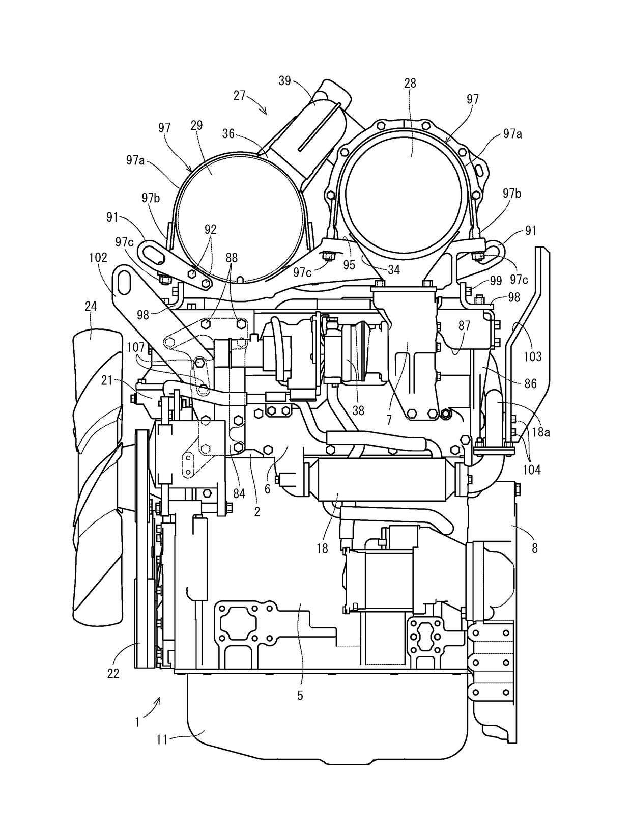
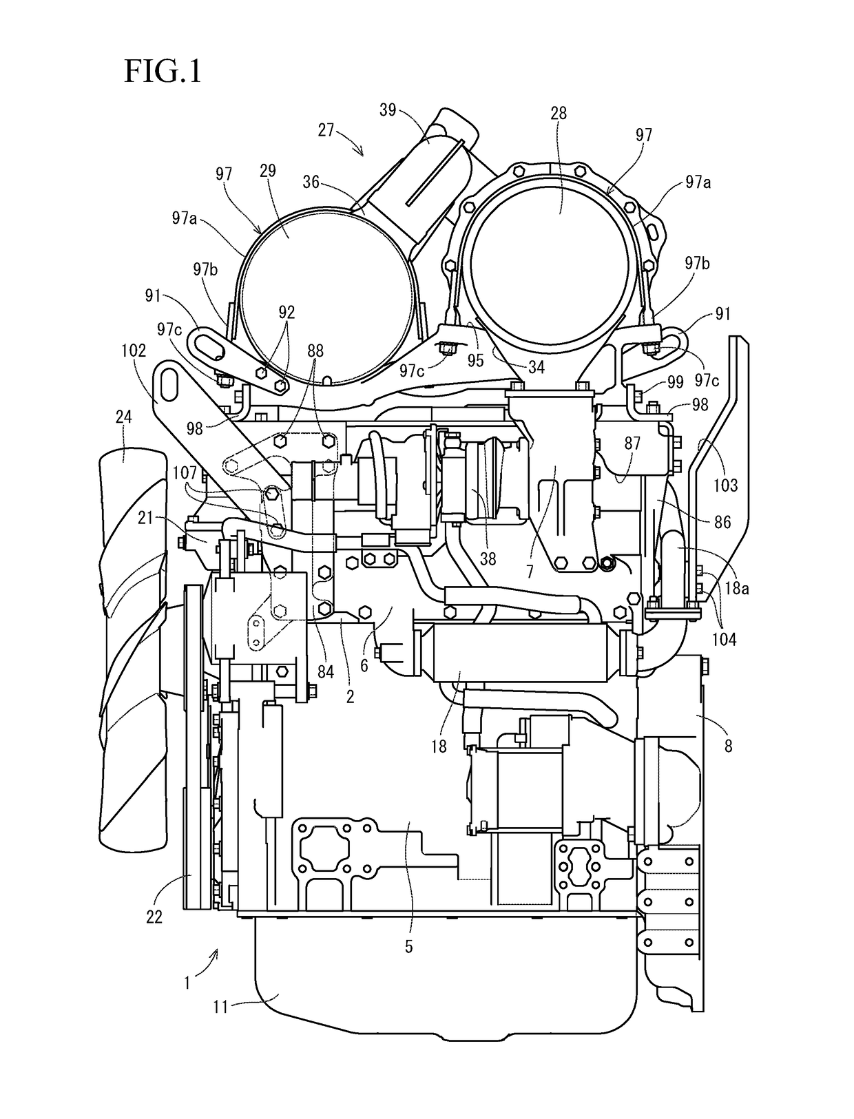
[0048]A description will be given below of a first embodiment obtained by embodying the present invention with reference to the accompanying drawings (FIGS. 1 to 20). FIG. 1 is a left side elevational view of a diesel engine 1 in which an exhaust gas manifold 6 is installed, FIG. 2 is a right side elevational view of the diesel engine 1 in which an intake air manifold 3 is installed, and FIG. 3 is a front elevational view of the diesel engine 1 in which a cooling fan 24 is installed. A side in which the exhaust gas manifold 6 is installed is called as a left side surface of the diesel engine 1, a side in which the intake air manifold 3 is installed is called as a right side surface of the diesel engine 1, and a side in which the cooling fan 24 is installed is called as a front surface of the diesel engine 1.

[0049]A description will be given of a whole structure of the diesel engine 1 with reference to FIGS. 1 to 5. As shown in FIGS. 1 to 5, an intake air manifold 3 is arranged in on...


PUM


Abstract

In the engine device having an exhaust gas purification device which removes particulate matters in exhaust gas of the engine or nitrogen oxides in the exhaust gas of the engine, the exhaust gas purification device is firmly fixed to a support base, and an exhaust gas outlet pipe of the engine is provided with an exhaust connection portion which connects an exhaust gas inlet of the exhaust gas purification device, and a support base connection portion which connects the support base.

Description

CROSS-REFERENCE TO RELATED APPLICATIONS[0001]The present application is a continuation application of International Application No. PCT / JP2015 / 077302, filed Sep. 28, 2015, which claims priority to Japanese Patent Application No. 2014-205770, filed Oct. 6, 2014 and Japanese Patent Application No. 2014-205771, filed Oct. 6, 2014. The contents of these applications are incorporated herein by reference in their entirety.BACKGROUND OF THE INVENTION[0002]The present invention relates to an engine device.[0003]There has been conventionally known a technique of purifying the exhaust gas discharged from the diesel engine by arranging a case inward provided with a diesel particulate filter (hereinafter, refer to as a DPF case), and a case inward provided with a urea selective reducing type catalyst (hereinafter, refer to as an SCR case), as an exhaust gas purification device (an exhaust gas aftertreatment device) in an exhaust channel of the diesel engine, and introducing the exhaust gas to t...

Claims


Application Information

Patent Timeline
Patent Type & Authority Applications(United States)
IPC IPC(8): F01N3/28F01N3/20F01N13/10B60K13/04F02M26/23F02M26/03B60K5/12F01N3/021F02M26/15
CPCF01N3/2839F01N3/0211F01N3/2066F01N13/10B60K13/04F02M26/23F02M26/03B60K5/1208F02M26/15F01N3/08F01N3/24F01N3/28F01N13/1805F01N13/1838F01N3/021F01N2590/08Y02A50/20Y02T10/12B60Y2200/22B60Y2200/41
Inventor KIMURA, TOMOYUKI
Owner YANMAR POWER TECHNOLOGY CO LTD
Why Eureka
Try Eureka