Heat exchanger and method of manufacturing the same

a technology of heat exchanger and insulating plate, which is applied in the direction of manufacturing tools, soldering devices, light and heating apparatus, etc., can solve the problems of insufficient melted flux reaching the inner fin to break up (destabilize or disrupt) the oxide film, and the inner fin may be unstable, etc., to achieve strong, effective brazing joints (fillets, easy to prepar

Inactive Publication Date: 2017-07-20
FURUKAWA SKY ALUMINUM CORP
View PDF9 Cites 5 Cited by
  • Summary
  • Abstract
  • Description
  • Claims
  • Application Information

AI Technical Summary

Benefits of technology

[0021]In certain embodiments of the present teachings, the object to be processed (brazed) may be heated in an inert-gas atmosphere and the brazing can be performed without using any flux in the interior of the hollow structure where the oxygen concentration is comparatively low. On the other hand, the brazing can be performed using a flux according to the present teachings on the outside (exterior) portions of the hollow structure where the oxygen concentration may be comparatively high during the brazing process. As a result, durable and robust heat exchangers having strong, effective brazed joints (fillets) both within the interior and around the exterior of the heat exchanger can be easily prepared.

Problems solved by technology

In this case, the melted K—Al—F-based flux may contact Mg on the surface of the inner fin and consume it without breaking up the oxide film on the inner fin and / or interior surface of the hollow structure, thereby inhibiting the intended fluxless brazing of the inner fin to the hollow structure.
However, because only a relatively small amount of the melted flux will penetrate into the interior of the hollow structure, insufficient melted flux reaches the inner fin to break up (destabilize or disrupt) the oxide films on the inner fin and / or the portion of the interior surface of the hollow structure that contacts the inner fin prior to formation of the fillets.
Therefore, the technique of JP 2004-25297 is problematic, because unstable fillets may form at the parts to be joined inside the hollow structure, such as, e.g., the interior surface(s) of the hollow structure that will be joined with the inner fin, due to the impairment of the brazing process caused by the insufficiently broken-up oxide films.
In addition, the technique of JP 2013-233552 is problematic in that brazeability degrades if the brazing atmosphere has a relatively high concentration of oxygen.
On the other hand, because the oxygen concentration inside the brazing furnace typically fluctuates during the brazing process owing to various factors, it is difficult to constantly maintain a low oxygen concentration outside of the hollow structure throughout the entire brazing process.
Consequently, the brazeability of parts on the exterior of the hollow structure that are directly exposed to the brazing furnace atmosphere, such as, e.g., portions of the outer walls (contact part) of the hollow structure that will be joined to each other, tends to degrade.
However, this means there is a risk that an insufficient amount of the filler material will remain on the outer side (exterior) of the hollow structure, thereby leading to inferior brazed joints and possible brazing failures (defects), such as tearing of fillets, on exterior portions of the hollow structure.

Method used


Image

  • Heat exchanger and method of manufacturing the same
  • Heat exchanger and method of manufacturing the same
  • Heat exchanger and method of manufacturing the same

Examples


working examples

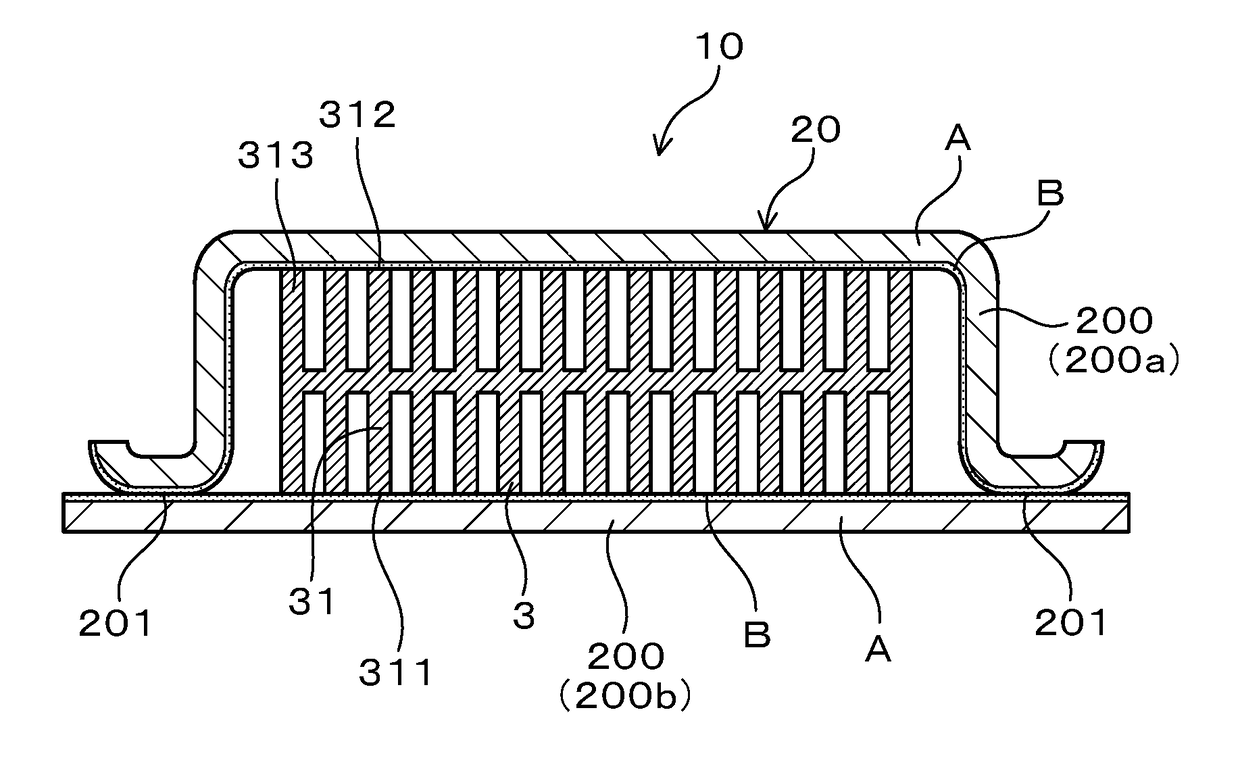
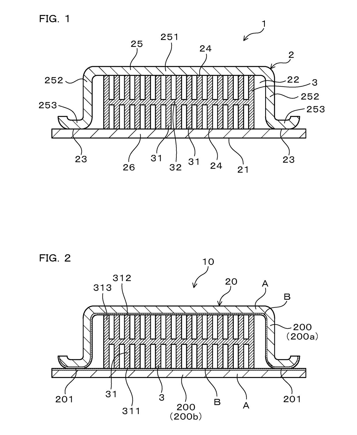
[0093]A representative heat exchanger and a representative method of manufacturing the same will now be explained with reference to the drawings. As shown in FIG. 1, the heat exchanger 1 of the present example comprises: a jacket 2, in which a heat-generating-element mounting surface 21, on which one or more heat-generating elements is (are) to be mounted, is provided (defined) on an outer surface thereof and a coolant passageway 22, through which a coolant circulates (flows), is provided (defined) in the interior; and an inner fin 3 disposed in the coolant passageway 22. The jacket 2 is preferably composed of a plate material having a chemical composition that contains Mg: 0.40-1.0 mass %, the remainder being Al and unavoidable impurities. However, other elements optionally may be added to the alloy composition of the jacket 2, as was discussed above and will be further discussed below. The inner fin 3 is formed by extruding an aluminum alloy having a chemical composition that pref...

experimental examples

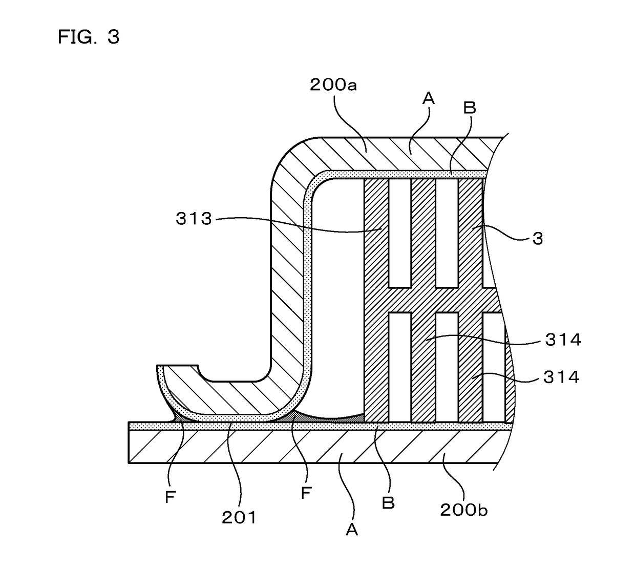
[0108]The following experimental examples are additional examples (both inventive and comparative) of the heat exchanger 1 in which the chemical compositions of the core layer A, the filler-material layer B, and the aluminum alloy that constitutes the inner fin 3 have been variously modified. It is noted that the components of the heat exchangers 1 manufactured in the present examples have the same shape as in the above-described working example. It is noted that the reference numbers and letters used in the following experimental examples are the same as were used in FIG. 1 to FIG. 3 to indicate the same structural elements, etc. as in the working example, except as otherwise explained.

[0109]In the present examples, the clad plates 200 and the inner fin 3 were manufactured as described below.

[0110]Clad Plates 200

[0111]Aluminum alloys (A1-A7) having the chemical compositions listed in Table 1 were cast into ingots. The resulting ingots were heated to 560° C. and a homogenization tre...


PUM

PropertyMeasurementUnit
thicknessaaaaaaaaaa
thermal decomposition temperatureaaaaaaaaaa
temperatureaaaaaaaaaa

Abstract

A method for manufacturing a heat exchanger (1) includes joining an inner fin (3) to a hollow structure (20) formed from at least two clad plates (200a, 200b) by heating and brazing a filler metal layer (B). Each clad plate has a core layer (A) composed of an aluminum alloy that contains Mg: 0.40-1.0 mass %. The filler metal layer is composed of an aluminum alloy that contains Si: 4.0-13.0 mass %, and further contains Li: 0.0040-0.10 mass %, Be: 0.0040-0.10 mass %, and/or Bi: 0.01-0.30 mass %. The inner fin is composed of an aluminum alloy that contains Si: 0.30-0.70 mass % and Mg: 0.35-0.80 mass %. A flux (F) that contains cesium (Cs) is applied along a contact part (201), and the vicinity thereof, of the at least two clad plates prior to the heating. A heat exchanger (1) may be manufactured according to this method.

Description

CROSS-REFERENCE[0001]This application claims priority to Japanese patent application no. 2016-5554 filed on Jan. 14, 2016, the contents of which are fully incorporated herein by reference.TECHNICAL FIELD[0002]The present invention relates to a heat exchanger and to a method of manufacturing the same.BACKGROUND ART[0003]Inverter units are used in various applications such as in the control of a drive motor of, for example, a hybrid automobile, an electric vehicle, or the like. An inverter unit comprises a semiconductor (switch) device, such as an IGBT (insulated gate bipolar transistor), and a heat exchanger for cooling the semiconductor device as well as other heat-generating elements (bodies) such as electronic parts that constitute the power conversion circuit.[0004]Such a known heat exchanger comprises a hollow structure having an outer surface defining a mounting surface, on which a heat-generating element (body) is mounted, and an inner fin housed in the interior of the hollow ...

Claims


Application Information

Patent Timeline
Patent Type & Authority Applications(United States)
IPC IPC(8): F28F21/08F28F3/06
CPCF28F21/084F28F2275/04F28F21/089F28F3/06B23K1/008B23K1/19B23K1/20B23K35/30F28F21/081B23K2101/14B23K1/0012B23K1/203B23K35/286B23K35/288B23K35/36B23K35/3603B23K35/3605B23K35/383B23K35/002B23K35/0222B23K35/0233B23K35/0238B23K35/0244B23K35/025B32B15/016C22C21/02C22C21/06C22C21/08C22C21/10F28D1/0206F28D2021/0029
Inventor YANAGAWA, YUTAKAISOMURA, NORIHISATOTANI, YUKIYAGITA, YASUHIROHATA, TETSURO
Owner FURUKAWA SKY ALUMINUM CORP
Why Eureka
Try Eureka