Optimised heat pump system

Inactive Publication Date: 2017-07-27
SHARP KK
View PDF0 Cites 44 Cited by
  • Summary
  • Abstract
  • Description
  • Claims
  • Application Information

AI Technical Summary

Benefits of technology

[0019]In the present invention, the system controller expands the available range of heat demanded by the system using minimum and maximum profiles for comfortable temperatures. This is not normally done, for example, in the case of heating with a gas boiler where any extra heating beyond the minimum set-point leads to increased losses and higher operating costs.
[0020]The expande

Problems solved by technology

Also, increasing heating or cooling beyond the mean comfortable level increases exergetic losses from a temperature-regulated space.
Therefore, marginal increases in stored energy impose ever-greater marginal costs.
Additionally, for a system with fixed capacities of heat absorbers and heat emitters, stable heat pump output yields the maximum average COP (Coefficient of Performance).
Lower power consumption during other periods does increase COP but it does not fully compensate for the degradation in performance during high power consumption periods.Predictability: To cost-efficiently apportion heat transfer throughout a day, it is necessa

Method used


Image

  • Optimised heat pump system
  • Optimised heat pump system
  • Optimised heat pump system

Examples


first embodiment

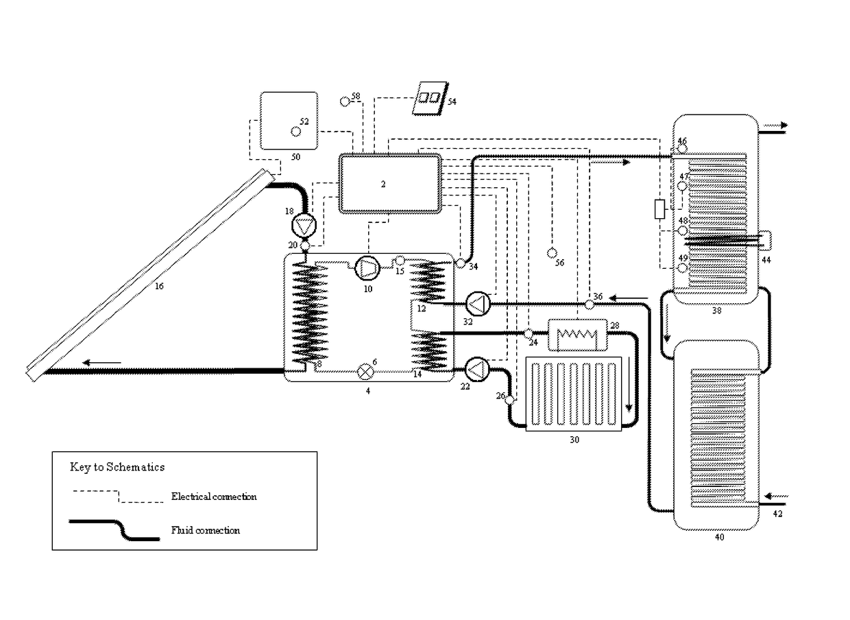
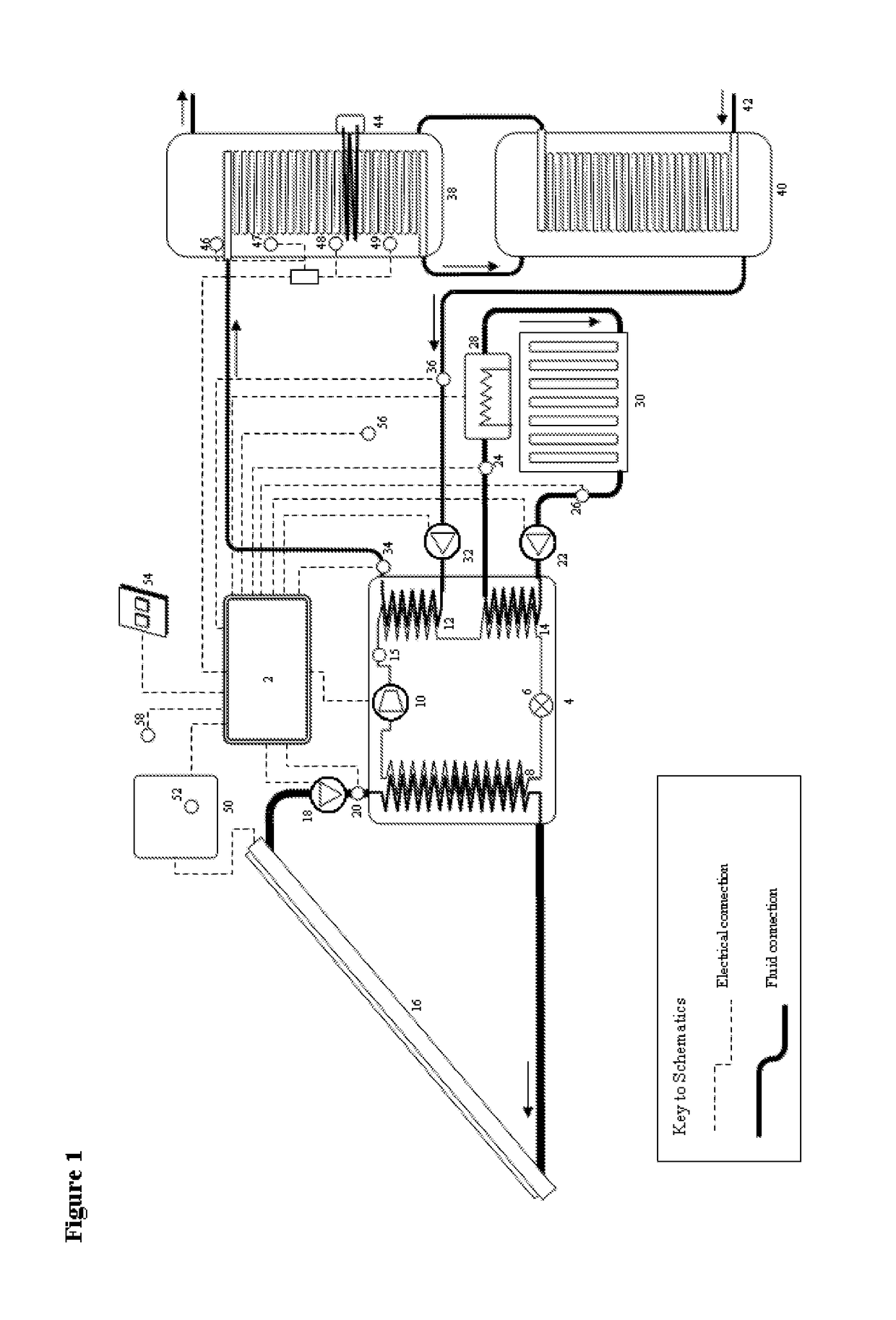
[0079]In exemplary embodiments of the present invention, FIG. 1, a system controller 2 (herein termed “the controller”) regulates a heat pump 4 which comprises a vapour-compression cycle for transferring heat from a heat source to a heat load.

[0080]The refrigeration circuit shown in FIG. 1 follows a ‘dual temperature’ heat pump design. At the start of the cycle, a refrigerant is expanded by an electronically-controlled expansion valve 6 to drop its evaporating temperature to below the source fluid return temperature such that it can absorb heat from a source fluid by evaporating said refrigerant in an evaporator 8. The refrigerant vapour is subsequently compressed by a compressor 10 with an inverter-driven electric motor, and through a desuperheater 12 that is cooled in contraflow heat exchange by a minor fluid circuit, and then subsequently passed through a condenser 14 that is cooled by a major circuit before re-entering the expansion valve 6. The evaporator, desuperheater and con...

second embodiment

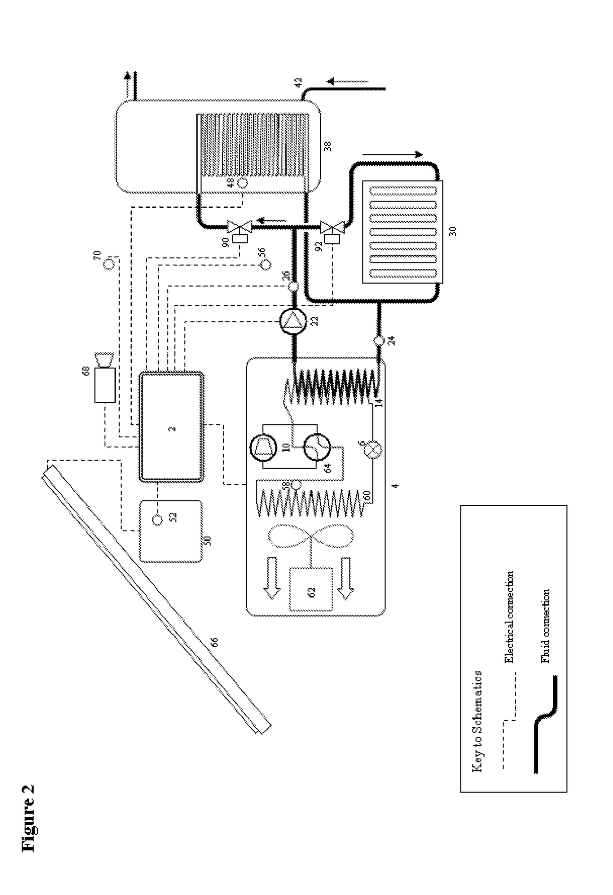
[0144]In a second embodiment of the invention, FIG. 2, the heat pump 4 includes a motorized electric fan 62 which is arranged to propel air through a finned-coil evaporator 60 in the manner of an “air-source heat pump”. In this embodiment the outdoor air temperature sensor is preferably mounted at the intake vent to the evaporator. The refrigeration circuit comprises only one condenser 14 which may supply heat to either a space heating circuit or a hot water tank 38 as regulated by the switching of two motorized valves including a hot water zone valve 90 and a space heating output zone valve 92. The refrigeration circuit also contains a 4-way reversing valve 64, which is arranged in the configuration illustrated in EP0134015B1 (1984) and permits the source and load circuits to be reversed such that heat can be extracted from the ‘load’ and rejected to the ‘source’. This design of heat pump enables the load circuit to perform either heating or cooling functions, thus expanding the ab...

third embodiment

[0153]In a third embodiment of the invention, FIG. 3, heat collectors, which may be plastic pipes that form a ground source heat exchange loop 72, are mounted in the ground in the manner of a “ground-source heat pump” system, and a circulating pump 18 transports heated coolant from the heat collectors to the heat pump evaporator 8. Ground source collectors provide a more stable temperature over daily and seasonal periods compared to air and solar-source collectors, which assist the ability of the controller to predict the net cost of heat and devise more optimised heating plans. The disadvantages of ground source collectors are the high installation and maintenance costs compared to other heat sources, and the relatively low source temperatures which are available during the summer.

[0154]The controller monitors the AC power output of a wind turbine generator 74 with a current transformer used as the electric generator power output sensor 52. The measured AC power is connected to the...


PUM


Abstract

A system for space heating or cooling a heated space includes a heat pump including a refrigeration circuit for transferring heat between a heat source and a heat load for heating and cooling operations. A controller controls the heat pump to perform the heating and cooling operations. A user interface receives user inputs, wherein the user inputs include an indication of discomfort based on temperature. The controller creates a profile for a minimum comfortable temperature level and a maximum comfortable temperature level, and the controller controls the heat pump to perform the heating and cooling operations in accordance with the profiles for the minimum and maximum comfortable temperature levels. The controller may generate an optimized heat demand plan in accordance with predictions of outdoor and indoor temperature, cost, and demand. The plan is optimized to cost-effectively maintain the temperature of the heated space within the comfortable temperature range defined by the profiles.

Description

TECHNICAL FIELD[0001]This invention relates to heat pump systems, controllers and their user interfaces, and in particular electrical heat pump systems with a variable cost source of electricity, such as photovoltaic panels.BACKGROUND ART[0002]Heat pumps are known to be an efficient means of facilitating heating or cooling applications, comparing favourably against the primary energy requirements of fossil fuel or biomass boilers. Improved efficiency is considered desirable to consumers as it can deliver lower operating costs. With respect to all HVAC (Heating, Ventilation and Air-Conditioning) systems, it is well-accepted that costs can also be lowered by reducing the amount of heat that must be added or removed from a building. However, reducing heating or cooling demands can leave occupants thermally uncomfortable, so the user of an HVAC system will generally target a compromise between thermal comfort and cost.[0003]For heat pump systems, the daily cost of heat transfer is an in...

Claims


Application Information

Patent Timeline
IPC IPC(8): F24F11/00F25B30/02F24D19/10F24D12/00F24D15/04
CPCF24F11/006F24D12/00F24D15/04F24D19/10F25B30/02F24F2005/0057F24F11/0012F24F2011/0013F24F2011/0075F24F2005/0067F24F2011/0045Y02B10/40Y02B10/70F25B6/04F25B40/04F24D19/1072F24D19/1081G05D23/1923F24D2200/02F24D2200/11F24D2200/123F24D2200/15F24D2220/042F24D2220/08F24D2240/26F24F11/30F24F2110/10F24F2110/12F24F2140/20F24F11/62F24F11/46F24F11/84F24F2120/00F24F11/47F24F11/65F24F11/52F24H15/172F24H15/215F24H15/219F24H15/277F24H15/254F24H15/227F24H15/281F24H15/38F24H15/225F24H15/176F24H15/258F24H15/16
Inventor SLACK, RICHARDTOMLIN, MICHAELBARRETT, JACOBNONWEILER, JOHN
Owner SHARP KK
Why Eureka
Try Eureka