Eureka AIR delivers breakthrough ideas for toughest innovation challenges, trusted by R&D personnel around the world.

Small load-following nuclear power generation system using heat deformation of reflector caused by thermal expansion phenomenon

Active Publication Date: 2017-07-27
CLEAR
View PDF3 Cites 13 Cited by
  • Summary
  • Abstract
  • Description
  • Claims
  • Application Information

AI Technical Summary

Benefits of technology

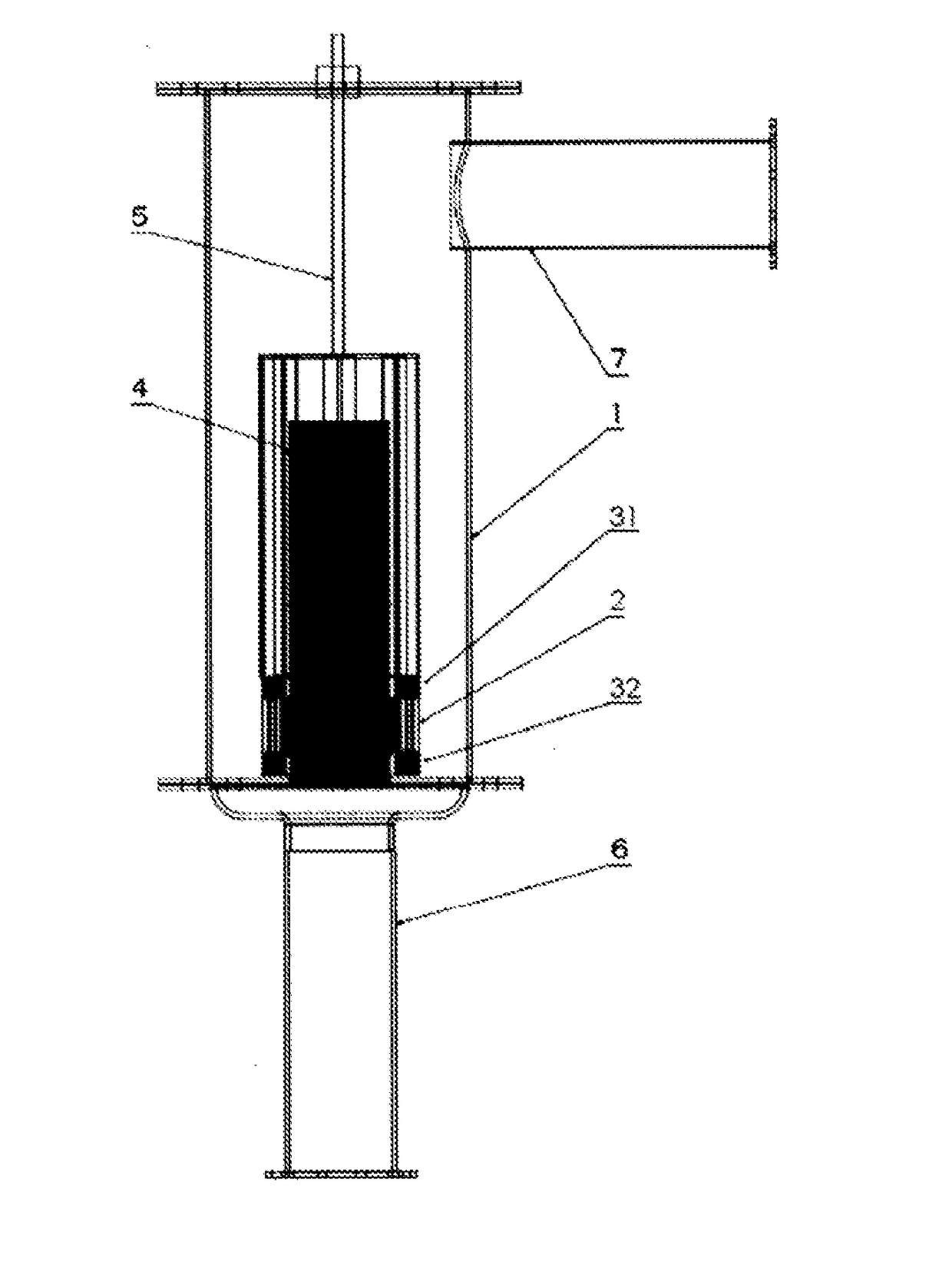
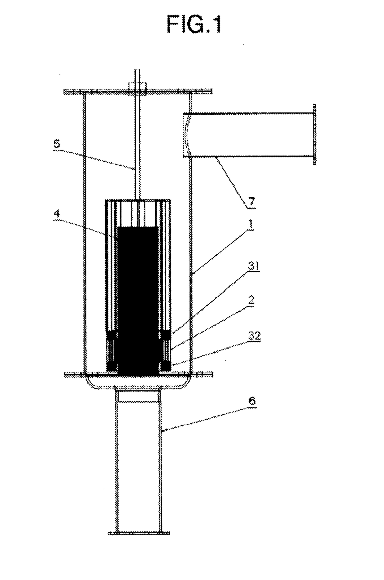
The present invention is for a small nuclear reactor system that uses metallic sodium as a primary coolant and can automatically control its reactivity based on changes in power demands. The system has a small reactor vessel with fuel rod assemblies and a pump to circulate the primary coolant. The heated primary coolant is then supplied to an external heat exchanger where it is cooled by a secondary coolant. The secondary coolant is driven by a turbine, which can be much smaller and more efficient than previous systems, resulting in a smaller and more efficient power generation system.

Problems solved by technology

In such a large nuclear reactor having control rods, a loss of the control of rod functionality due to, for example, trouble in the mechanism of controlling the positions of the control rods may cause a runaway of nuclear reactions in the reactor core.

Method used


Image

  • Small load-following nuclear power generation system using heat deformation of reflector caused by thermal expansion phenomenon
  • Small load-following nuclear power generation system using heat deformation of reflector caused by thermal expansion phenomenon
  • Small load-following nuclear power generation system using heat deformation of reflector caused by thermal expansion phenomenon

Examples


first embodiment

[0095]The reflector, which is a key feature for load following control in the present invention, will now be described with reference to FIGS. 3A, 3B, and 4. As illustrated in FIG. 3A, the reflector has a double wall structure in which both walls made of graphite have a thickness of 10 cm. The reflector is circumferentially divided into eight sections of two types: reflectors A 21 and reflectors B 22. The two types of reflectors alternate and have different radiuses. This double wall structure is capable of accommodating one wall of adjacent reflectors each other when the reflectors are circumferentially shifted. As illustrated in FIG. 3B, the double wall structure having the reflectors A 21 and the reflectors B 22 is fixed by reflector support plates 20. The reflectors B 22 have an inner diameter of 52 cm and a height of 50 cm. These two types of reflectors in the double wall structure are shifted to each other to form gaps (slits) between the reflectors A 21 and the reflectors B 2...

second embodiment

[0099]A way of increasing the temperature of the critical point, at which Keff reaches 1, will now be described. As illustrated in FIG. 7, the four reflectors A 21 and the four reflectors B 22 into which a reflector is divided are provided, and these reflectors have overlaps 23. The slit widths associated with the thermal expansion in the reflectors are adjusted using the overlaps. FIG. 8 shows the calculations of Keff and the slit widths associated with the thermal expansion when the reflectors have overlaps. As is apparent from the drawing, the temperature at which Keff reaches 1 increased to about 500° C. In this manner, adjusting the lengths of the overlaps in the division reflectors allows the temperature at which Keff reaches 1 to be adjusted.

third embodiment

[0100]FIG. 9 illustrates still another embodiment of the reflector structure according to the present invention. The first and second embodiments shift the division reflectors circumferentially to create each slit between reflectors, thereby controlling Keff. The present embodiment moves reflectors radially to control Keff. The mechanism will be described with reference to FIG. 9. In order that double-wall reflectors 21, 22, which are eight divisions, can move away from the fuel assemblies with rising temperature, the thermal expansion of adjustment springs 26 is used. First, a fixation cylinder 24 for fixing the adjustment springs 26 is provided outside the eight divisional double-wall reflectors 21, 22. Next, eight spring drive reflector moving jigs for as many division reflectors are mounted outside the fixation cylinder, and each jig has a combination of an adjustment spring support plate 27, a reflector adjusting rod 28, and an adjustment spring 26. The support plate 27 receive...


PUM


Abstract

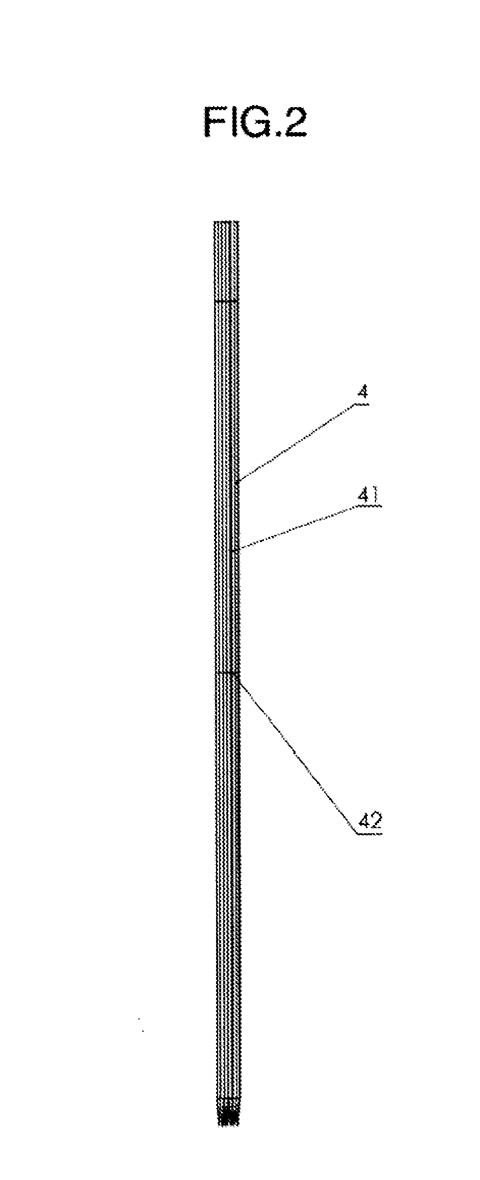
The present invention provides a small nuclear power generation system being safe and easily controlled by load following, and allowing reductions in manufacturing costs and maintenance and management costs. The small nuclear power generation system has a small nuclear reactor employing a load following control method. The reactor includes: a fuel assembly reactor core 4 having metallic fuel containing one or both of uranium (235, 238) and plutonium-239; a reactor vessel 1 containing the fuel assembly reactor core 4; metallic sodium loaded into the reactor vessel 1 and heated by the fuel assembly reactor core 4; and a neutron reflector 2 for achieving criticality in the reactor core with effective multiplication factor of neutrons emitted from the fuel assembly reactor core 4 being maintained at or above about 1. The load following control method of the reactor allows a neutron effective multiplication factor to be controlled by coupling the neutron reflector to spring or spiral metallic members and utilizing heat deformation in the metallic members due to the temperature in coolant metallic sodium to control the fast neutron reflection efficiency of the neutron reflector

Description

INCORPORATION BY REFERENCE[0001]This application claims priority based on Japanese Patent Application No. 2015-75942 filed on Apr. 2, 2015, the disclosure of which is incorporated herein by reference.TECHNICAL FIELD[0002]The present invention relates to a small nuclear power generation system, and more particularly to a small nuclear power generation system having cooling systems that are at least separated to primary and secondary systems and including a load following control system in which a nuclear reaction in a small nuclear reactor is automatically controlled.BACKGROUND ART[0003]Known examples of nuclear reactors in nuclear power generation systems include an indirect-cycle reactor for generating electricity by rotating a turbine with radiation-uncontaminated water vapor. Such a nuclear reactor has steam generators and heat exchangers between the primary and secondary cooling systems.[0004]A loop-type fast reactor intended for the construction of a large power generation syst...

Claims


Application Information

Patent Timeline
IPC IPC(8): G21D3/12G21C7/10G21D3/16
CPCG21D3/12G21D3/16G21C7/10G21D3/08G21Y2004/40G21C7/00G21Y2002/201G21C1/02G21C7/28G21C1/06G21C7/02G21C11/06G21C3/60G21C5/00G21C7/24G21D5/14Y02E30/30
Inventor SUMITA, OSAOUENO, ISAOYOKOMINE, TAKEHIKO
Owner CLEAR
Why Eureka
Eureka Blog
Learn More