Liquid feeding device for the generation of droplets

a liquid feeding device and droplet technology, applied in the direction of granulation using vibration, antibody medical ingredients, lighting and heating apparatus, etc., can solve the problems of mono-sized droplets, mixing, filling and drying processes that cannot normally be separated, and the change of composition mixing ratio after filling into the vial is practically impossible, so as to reduce the permanent magnetic properties, facilitate the receipt of fda certificates, and simplify the inner structure of the liquid feeding devi

Active Publication Date: 2017-08-03
SANOFI PASTEUR SA
View PDF13 Cites 4 Cited by
  • Summary
  • Abstract
  • Description
  • Claims
  • Application Information

AI Technical Summary

Benefits of technology

[0038]Various embodiments of the present invention provide one or more of the advantages discussed hereafter. For example, with the liquid feeding device as presented herein, it is possible to avoid all disadvantages of the known prior art. In particular, with the liquid feed device of the present invention, it becomes possible to achieve the desired product quality like particle size and particle size distribution in a very early stage of the production process.
[0039]Furthermore, with the stainless steel membrane of the presented liquid feeding device, receiving an FDA certificate may be facilitated compared to the known PTFE membranes or the like.
[0040]Moreover, mounting of the inner structure of the liquid feeding device is simplified, wherein it becomes possible to remove the magnet without difficulty compared to the known prior art in which the head of the nozzle with fixing of the electromagnetic coil has to be screwed together with the membrane flange and the nozzle body, such that a removal of the magnet during sterilization becomes impossible (heating reduces the permanent magnetic properties). Also, since the magnet as provided in the devices as known from the above cited prior art is glued to the membrane, fixing of the magnet on the membrane is weak such that, during disassembling and cleaning, the magnet it is often separated from the membrane and has to be glued again onto the membrane; also, a separation of the magnet from the membrane is facilitated by hot surfaces, which will be the case during sterilization. The thus heat sensitive magnet, however, needs to be in position all the time.
[0041]As a further advantage of the present invention, deaeration of the nozzle is possible with the structure of the liquid feeding device of the present

Problems solved by technology

A change in the mixing ratio of the composition after filling into the vials is practically not feasible.
The mixing, filling and drying processes therefore cannot normally be separated.
The resonance frequency, however, leads to monosized droplets.
However, the solution as proposed in U.S. Pat. No. 6,458,296 B1 exhibits certain undesired disadvantages, such as a lack of suitability for CiP (“Cleaning in Place”) and/or SiP (“Sterilization in Place”) requirements, a weak fixing of the magnet on the diaphragm, leading to easy separ

Method used


Image

  • Liquid feeding device for the generation of droplets
  • Liquid feeding device for the generation of droplets
  • Liquid feeding device for the generation of droplets

Examples


Embodiment Construction

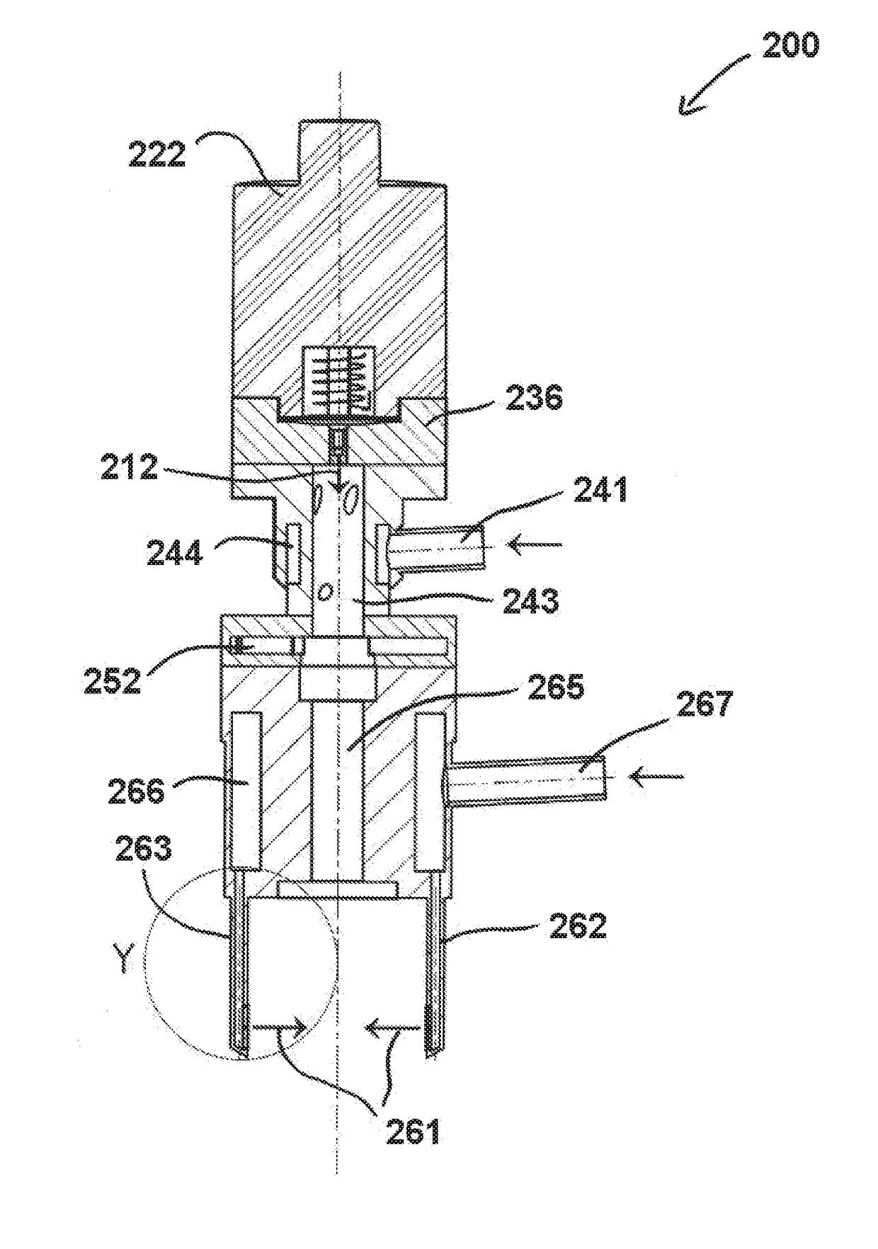
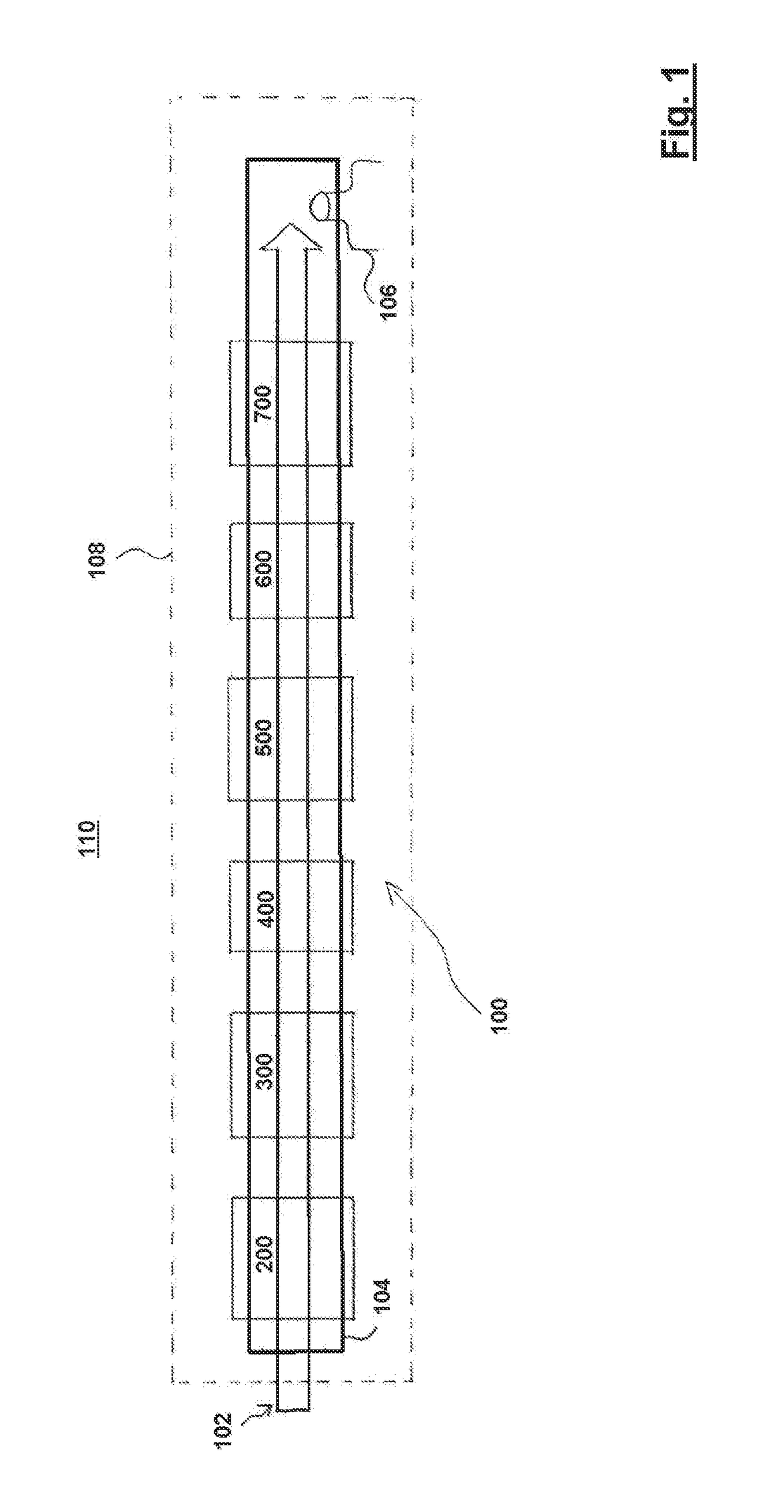
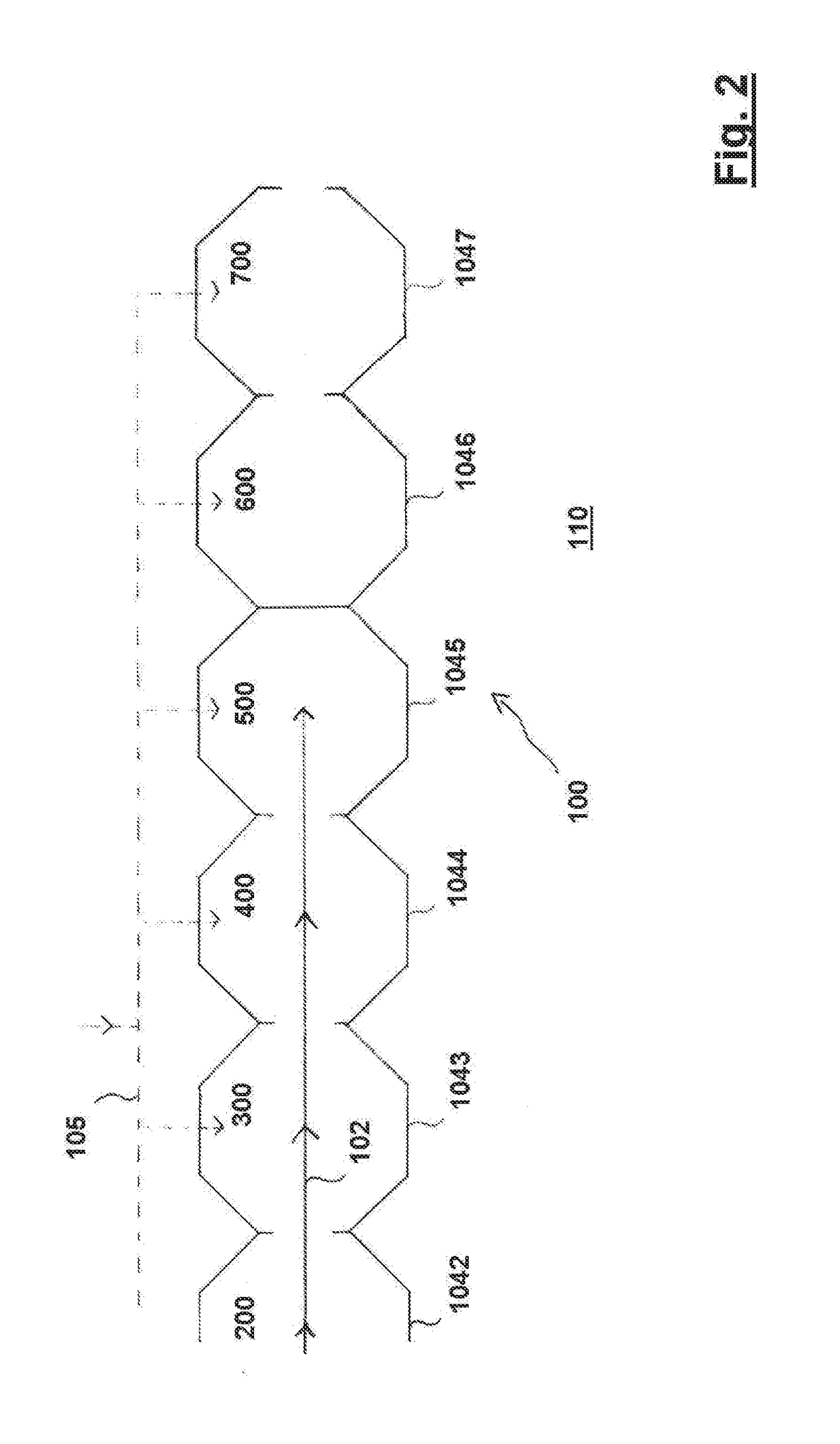
[0057]As a general overview, FIG. 1 schematically illustrates a process line 100 for the production of freeze-dried particles in the form of pellets, wherein a product flow 102 is assumed to pass through the process line 100 under closed conditions 104, also referred to as enclosure 104. A liquid feeding device 200 in accordance with a preferred embodiment of the present invention feeds liquid to a freezing chamber 300, also known as prilling chamber or prilling tower, in the form of ejected droplets (see also droplets 103 in FIG. 3), where the liquid is subjected to freeze-congealing. Frilling is a method of producing reasonably uniform spherical particles from liquid solutions. It essentially consists of two operations, firstly producing liquid droplets and secondly solidifying them individually by cooling. The prilling technology is also known as “laminar jet break-up” technology. The resulting frozen droplets are then transferred via a first transfer section 400 to a freeze-drye...


PUM

PropertyMeasurementUnit
Circumferenceaaaaaaaaaa
Levelaaaaaaaaaa
Sterileaaaaaaaaaa

Abstract

The present invention provides, inter alia, for a liquid feeding device for the generation of droplets, in particular for the use in a process line for the production of freeze-dried particles, with a droplet ejection section for ejecting liquid droplets in an ejection direction, the droplet ejection section comprising at least one inlet port for receiving a liquid to be ejected, a liquid chamber for retaining the liquid, and a nozzle for ejecting the liquid from the liquid chamber to form droplets, wherein the liquid chamber is restricted by a membrane on one side thereof, the membrane being vibratable by an excitation unit, wherein the longitudinal axis of the liquid chamber is tilted relative to the longitudinal axis of the nozzle, and/or the liquid feeding device further comprises a deflection section for separating the droplets from each other by means of at least one gas jet, wherein the deflection section gas jet intersects perpendicular with an ejection path of the liquid ejected from the liquid chamber.

Description

TECHNICAL FIELD[0001]The invention relates to the generation of droplets, in particular to be used for the production of freeze-dried pellets as bulkware, wherein a liquid feeding device is applied for the generation of droplets for the production of freeze-dried particles by means of a respective process line for droplet generation and freeze congealing of liquid droplets to form pellets.BACKGROUND OF THE INVENTION[0002]The production method generally referred to as freeze-drying, also known as lyophilization, is a process for drying high-quality products such as, for example, pharmaceuticals, biotechnology materials such as proteins, enzymes, microorganisms, and in general any thermo- and / or hydrolysis-sensitive material. With freeze-drying, the frozen product is usually dried via the sublimation of ice crystals into water vapor, i.e. via the direct transition of water content from the solid phase into the gas phase. Freeze-drying is often performed under vacuum conditions but wor...

Claims


Application Information

Patent Timeline
IPC IPC(8): F26B5/06A61K9/19A61K39/00B01J2/18B01J2/04
CPCF26B5/065B01J2/18A61K9/19A61K39/00B01J2/04B01D1/18
Inventor GEBHARD, THOMASKAISER, ROLANDLUY, BERNHARDPLITZKO, MATTHIASSTRUSCHKA, MANFREDZERILLO, CHRISTIAN
Owner SANOFI PASTEUR SA
Why Eureka
Try Eureka