Narrow band laser apparatus

Active Publication Date: 2017-08-03
GIGAPHOTON
View PDF8 Cites 5 Cited by
  • Summary
  • Abstract
  • Description
  • Claims
  • Application Information

AI Technical Summary

Benefits of technology

[0015]A narrow band laser apparatus according to an aspect of the present disclosure may include: a laser resonator including an optical element to narrow a spectral width; a pair of discharge electrodes disposed with an optical path of a pulse laser beam of the laser resonator interposed therebetween; a power supply configured to apply a pulsed voltage to the pair of discharge electrodes; a first wavelength measurement device configured to measure a wavelength of the pulse laser beam outputted from the laser resonator and output a first measurement result; a second wavelength measurement device configured to measure the wavelength of the pulse laser beam outputted from the laser resonator and output a second measurement result; and a control unit configured to calibrate the first measurement result, based on the second measurement result. The control unit calibrates the first measurement result, based on a difference between the second measurement result derived when the control unit controls the power supply to apply the pulsed voltage to the pair of discharge electrodes with a first repetition frequency and the second measurement result derived when the control unit controls the power supply to apply the pulsed voltage to the pair of discharge electrodes with a second repetition frequency, the

Problems solved by technology

This causes a chromatic aberration of a laser beam (ultraviolet light) that is subjected to reduced projection o

Method used


Image

  • Narrow band laser apparatus
  • Narrow band laser apparatus
  • Narrow band laser apparatus

Examples


first embodiment

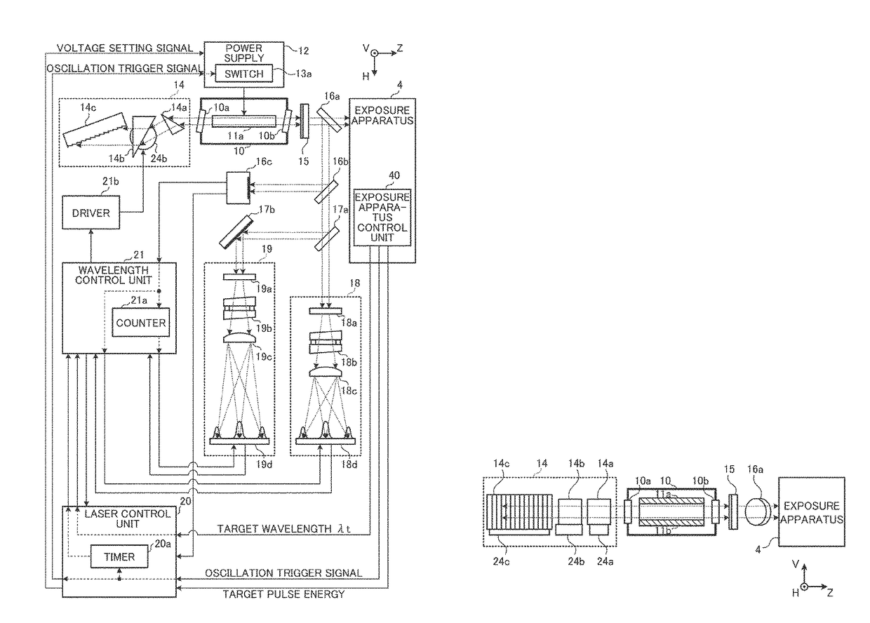
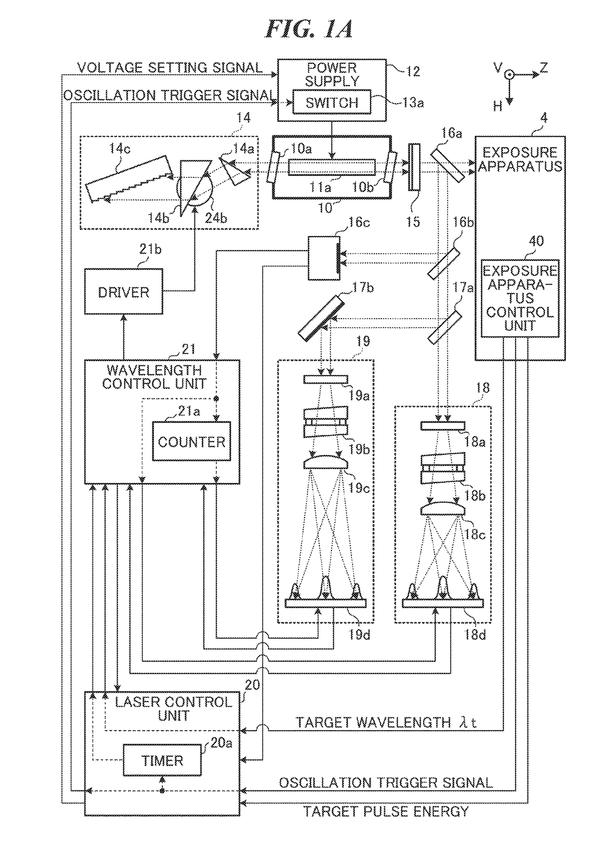
2. Narrow Band Laser Apparatus Including Wavelength Measurement Device (First Embodiment)

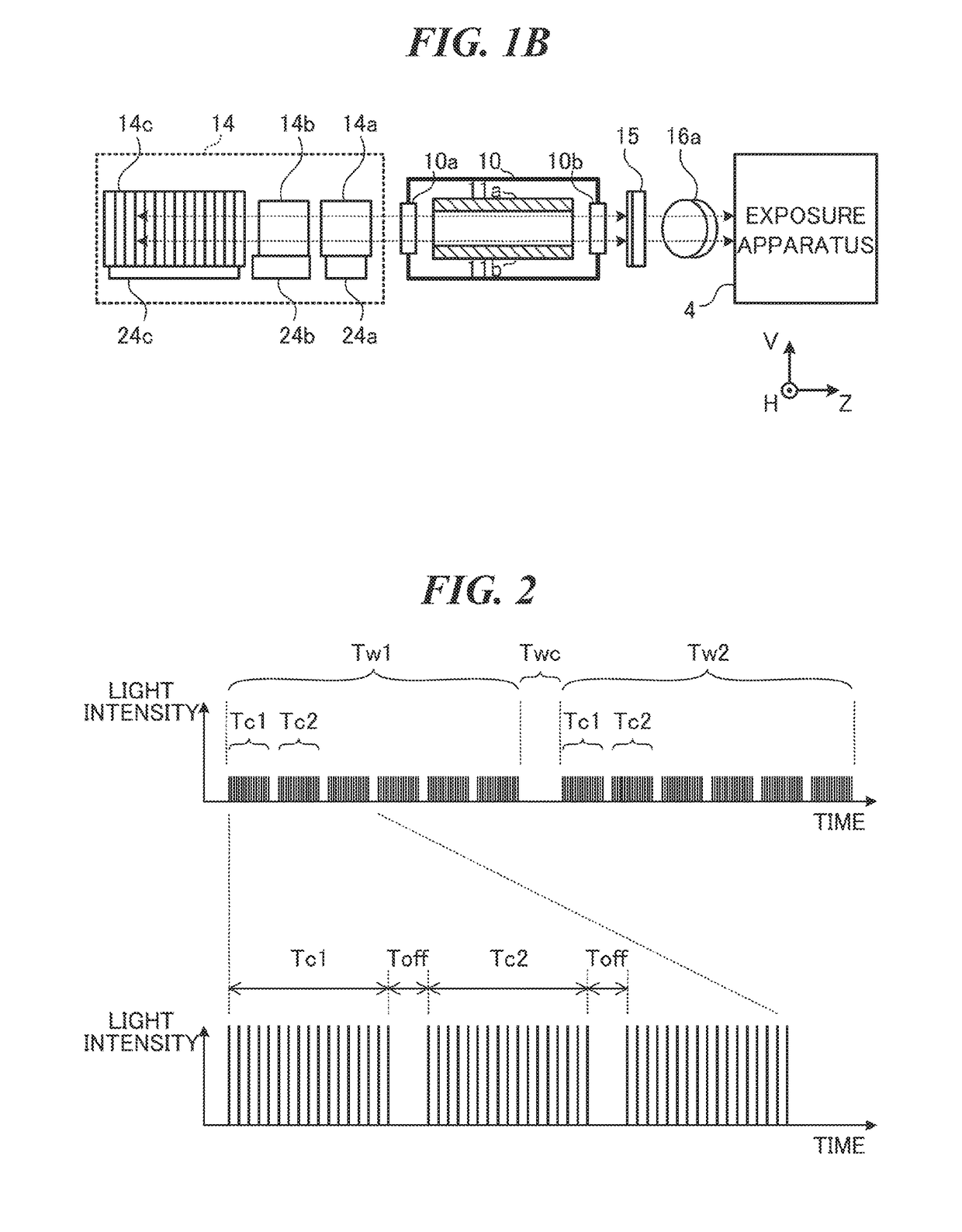
[0037]2.1 Laser Chamber[0038]2.2 Line Narrowing Module[0039]2.3 Output Coupling Mirror[0040]2.4 Energy Sensor[0041]2.5 Etalon Spectrometer[0042]2.6 Control Unit[0043]2.7 Output Pattern of Pulse Laser Beam[0044]2.8 Wavelength Control[0045]2.9 Flowchart[0046]2.9.1 Wavelength Control[0047]2.9.2 Calculation of Wavelength Offset Parameter

second embodiment

3. Variation of Calculation of Current Wavelength λ2 (Second Embodiment)

4. Variation of Calculation of Reference Wavelength λ20 (Third Embodiment)

fourth embodiment

5. Variation of Etalon Spectrometer (Fourth Embodiment)

6. Configuration of Control Unit

[0048]Embodiments of the present disclosure are described in detail below with reference to drawings. The embodiments described below illustrate some examples of the present disclosure and do not intend to limit contents of the present disclosure. In addition, all of configurations and operations described in the embodiments are not necessarily essential as components and operations of the present disclosure. Note that the same constituent elements are denoted by the same reference numerals and redundant description is omitted.

1. Outline

[0049]In an exposure apparatus that performs exposure with a double pattern or a triple pattern, a focal point of a reduced projection lens may change due to change in an oscillation wavelength of a narrow band laser apparatus. Therefore, control of a wavelength of the narrow band laser apparatus may be important. To control the wavelength, the narrow band laser ap...


PUM


Abstract

A narrow band laser apparatus may include: a laser resonator; a pair of discharge electrodes; a power supply; a first wavelength measurement device configured to output a first measurement result; a second wavelength measurement device configured to output a second measurement result; and a control unit. The control unit calibrates the first measurement result, based on a difference between the second measurement result derived when the control unit controls the power supply to apply a pulsed voltage to the pair of discharge electrodes with a first repetition frequency and the second measurement result derived when the control unit controls the power supply to apply the pulsed voltage to the pair of discharge electrodes with a second repetition frequency, the second repetition frequency being higher than the first repetition frequency.

Description

TECHNICAL FIELD[0001]The present disclosure relates to a narrow band laser apparatus.BACKGROUND ART[0002]The recent miniaturization and increased levels of integration of semiconductor integrated circuits has led to a demand for increases in the resolutions of semiconductor exposure devices. A semiconductor exposure device is referred to as an “exposure device” hereinafter. Accordingly, reduction of the wavelengths of light emitted from exposure light sources is improving. Typically, gas laser apparatuses are used as exposure light sources instead of conventional mercury lamps. For example, a KrF excimer laser apparatus that outputs an ultraviolet laser beam at a wavelength of 248 nm and an ArF excimer laser apparatus that outputs an ultraviolet laser beam at a wavelength of 193 nm are used as gas laser apparatuses for exposure.[0003]As a current exposure technology, immersion exposure has been put into practical use. In the immersion exposure, a gap between an exposure lens in an e...

Claims


Application Information

Patent Timeline
IPC IPC(8): H01S3/13H01S3/038H01S3/00G02B27/48H01S3/08
CPCH01S3/13G02B27/48H01S3/038H01S3/0071H01S3/08013G01J3/28H01S3/08009H01S3/08036H01S3/1305H01S3/134H01S3/137H01S3/2251H01S3/2256G01J1/0425G01J9/0246G01J2009/0257G01J1/0474H01S3/0811H01S3/0823H01S3/08004
Inventor MORIYA, MASATOOHTA, TAKESHIISHIDA, KEISUKEKUSAMA, TAKASHI
Owner GIGAPHOTON
Why Eureka
Try Eureka