Supercharge Your Innovation With Domain-Expert AI Agents!

Apparatus and method for motor braking in washing machine

a technology for washing machines and braking mechanisms, applied in the direction of electronic commutators, dynamo-electric converter control, stopping arrangements, etc., can solve the problems of unstable motor braking, inability to generate optimal braking torque, and inability to perform current control correctly, etc., to achieve stable control of the braking of the motor

Inactive Publication Date: 2017-08-17
DONGBU DAEWOO ELECTRONCIS CORP
View PDF2 Cites 8 Cited by
  • Summary
  • Abstract
  • Description
  • Claims
  • Application Information

AI Technical Summary

Benefits of technology

The present patent describes a way to control the braking of a washing machine's PM synchronous motor during braking, by calculating and applying a braking torque based on voltage limits set by the DC link capacitor and the inverter. This allows for stable control of the braking process during both low and high-speed operations of the washing machine.

Problems solved by technology

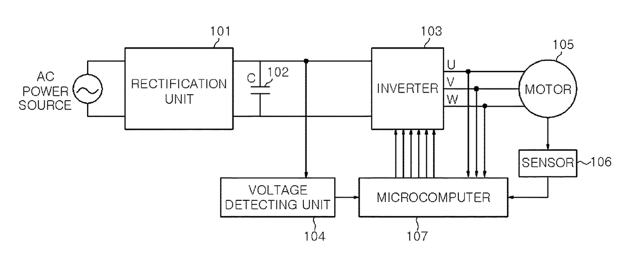
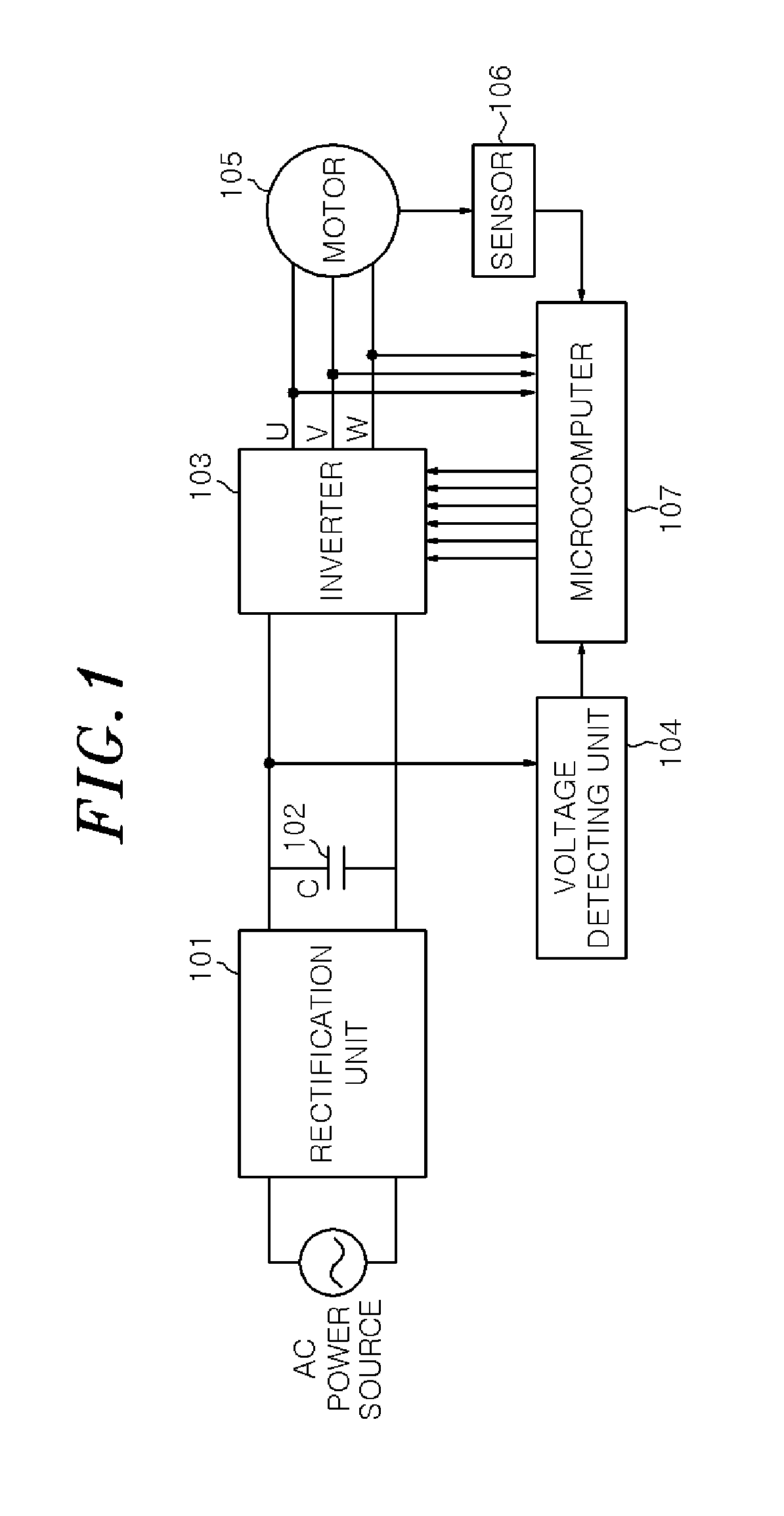
Unfortunately, the microcomputer 107 cannot generate an optimal braking torque during a high speed operation of the washing machine.
This is problematic because the conventional motor control system does not take into account a voltage limit of the inverter.
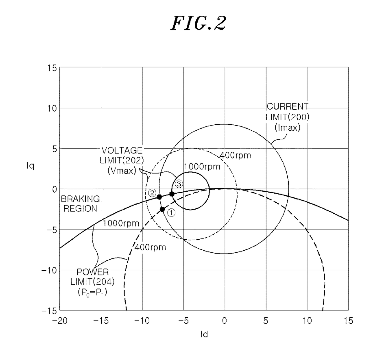
Thus, current control may not be performed correctly as the inverter 103 has a voltage limit and cannot supply a current corresponding to the braking operation point in the circled number (to the motor 105.
In this case, motor braking may be unstable.
However, if the motor 105 rotates at a high speed, the voltage and the current applied to the motor 105 from the inverter 103 may be limited due to the effect of the counter electromotive force.
If the voltage limit from the inverter 103 is not considered, the DC link voltage controller may not function correctly, thereby being unable to curb the rise of the voltage on the DC link capacitor 102.

Method used


Image

  • Apparatus and method for motor braking in washing machine
  • Apparatus and method for motor braking in washing machine
  • Apparatus and method for motor braking in washing machine

Examples


Embodiment Construction

[0026]In the following detailed description, reference is made to the accompanying drawings, which form a part hereof. The illustrative embodiments described in the detailed description, drawings, and claims are not meant to be limiting. Other embodiments may be utilized, and other changes may be made, without departing from the spirit or scope of the subject matter presented here.

[0027]One or more exemplary embodiments of the present disclosure will be described more fully hereinafter with reference to the accompanying drawings, in which one or more exemplary embodiments of the disclosure can be easily determined by those skilled in the art. As those skilled in the art will realize, the described exemplary embodiments may be modified in various different ways, all without departing from the spirit or scope of the present disclosure, which is not limited to the exemplary embodiments described herein.

[0028]It is noted that the drawings are schematic and are not necessarily dimensiona...


PUM


Abstract

A motor braking unit for a washing machine that offers high braking efficiency while preventing overcharging a capacitor in a DC link. The motor braking unit determines a current to be supplied to the motor based on a detected speed of the motor. The motor braking unit dynamically monitors the voltage on the capacitor against a reference voltage. If the capacitor voltage is lower than the reference voltage, the current component Iq is increased to increase the braking torque; and if the capacitor voltage is greater than the reference voltage, the current Iq component is decreased to prevent overcharging on the capacitor by the motor.

Description

CROSS-REFERENCE TO RELATED APPLICATION[0001]This application is based on and claims priority from Korean Patent Application No. 10-2016-0018031, filed on Feb. 16, 2016, the disclosure of which is incorporated herein in its entirety by reference for all purposes.TECHNICAL FIELD[0002]The present disclosure relates to washing machines, and in particular to a motor braking mechanism for washing machines.BACKGROUND OF THE INVENTION[0003]There is a trend in the washing machine market that a washing machine offers a variety of options of operational variety. Implementing various operational variety requires precise control over the motor in the washing machine.[0004]In general, a washing machine uses a motor and a control unit to drive the washing tub to rotate. For precise control over the motor, an inverter is typically used. FIG. 1 is a block diagram illustrating the configuration of a motor control system including an inverter in a washing machine.[0005]Referring to FIG. 1, the convent...

Claims


Application Information

Patent Timeline
IPC IPC(8): D06F37/30H02P6/08H02P6/17H02P21/36H02P27/06
CPCD06F37/306H02P21/36H02P6/08H02P6/17H02P27/06H02P6/24H02P2207/05H02P29/0241
Inventor JUNG, HEE SOKNAM, MYUNG JOONKIM, JONG HYUNCHO, KWAN YUHLKIM, HAG WONE
Owner DONGBU DAEWOO ELECTRONCIS CORP
Features
  • R&D
  • Intellectual Property
  • Life Sciences
  • Materials
  • Tech Scout
  • Unparalleled Data Quality
  • Higher Quality Content
  • 60% Fewer Hallucinations
Learn More