Light Reflecting Film, And Light Controlling Film, Optical Film, Functional Glass And Head-Up Display Including The Light Reflecting Film

a technology of light reflecting film and light controlling film, which is applied in the direction of polarizing elements, instruments, transportation and packaging, etc., can solve the problems of difficult application of members having high reflectance and other lows, and achieve the effect of improving the reflectance of only specific polarized light, improving the viewability of projected images, and maintaining high visible light transmittan

Active Publication Date: 2017-08-17
NIPPON KAYAKU CO LTD
View PDF9 Cites 32 Cited by
  • Summary
  • Abstract
  • Description
  • Claims
  • Application Information

AI Technical Summary

Benefits of technology

[0040]The light reflecting film of the present invention can improve viewability of a projected image of a HUD by effectively improving reflectance of only specific polarized light while maintaining high visible light transmittance, and in particular, for a case in which visible light transmittance is legally controlled, such as a windshield, it is possible to improve only viewability of a projected image of a HUD while maintaining the required visible light transmittance. ...

Problems solved by technology

However, transmittance and reflectance are normally in a trade-off relationship, and there is a drawback that if one of them is increased, the other becomes low.
Particularly, for an automotive w...

Method used


Image

  • Light Reflecting Film, And Light Controlling Film, Optical Film, Functional Glass And Head-Up Display Including The Light Reflecting Film
  • Light Reflecting Film, And Light Controlling Film, Optical Film, Functional Glass And Head-Up Display Including The Light Reflecting Film
  • Light Reflecting Film, And Light Controlling Film, Optical Film, Functional Glass And Head-Up Display Including The Light Reflecting Film

Examples


example 1

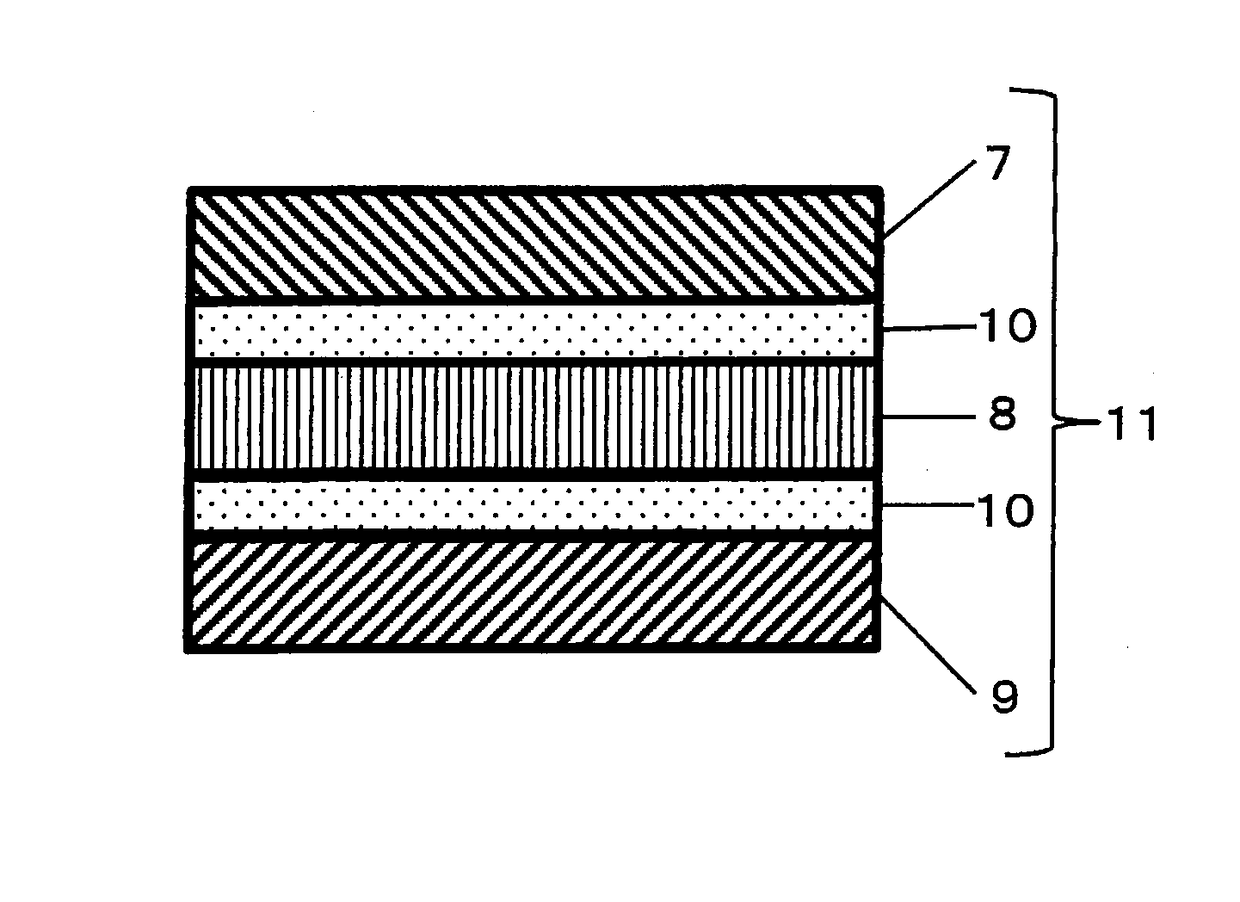
[0105]Using the coating solutions (R1), (R2) and (R3) thus prepared, light reflecting layers PRL-1, PRL-2, and PRL-3 were produced respectively with the following procedure. Subsequently, these were laminated to obtain the light reflecting film of the present invention. As a plastic substrate, a PET film (product name A4100, thickness 50 μm), manufactured by Toyobo Co., Ltd. was used, which has been subjected to a rubbing process in advance by a method described in Example 1 of Japanese Laid-Open Patent Publication No. 2002-90743 at a surface with no undercoat layer.

[0106](1) Using a wire bar, each of the coating solutions was applied to a rubbed surface of each of the PET films at room temperature such that each of light reflecting layers obtained after drying has a thickness of 0.5 μm.

[0107](2) Each coated layer was heated at 150° C. for five minutes to remove the solvent and made into a cholesteric liquid-crystalline phase. Then, UV irradiation was carried out with an output powe...

example 2

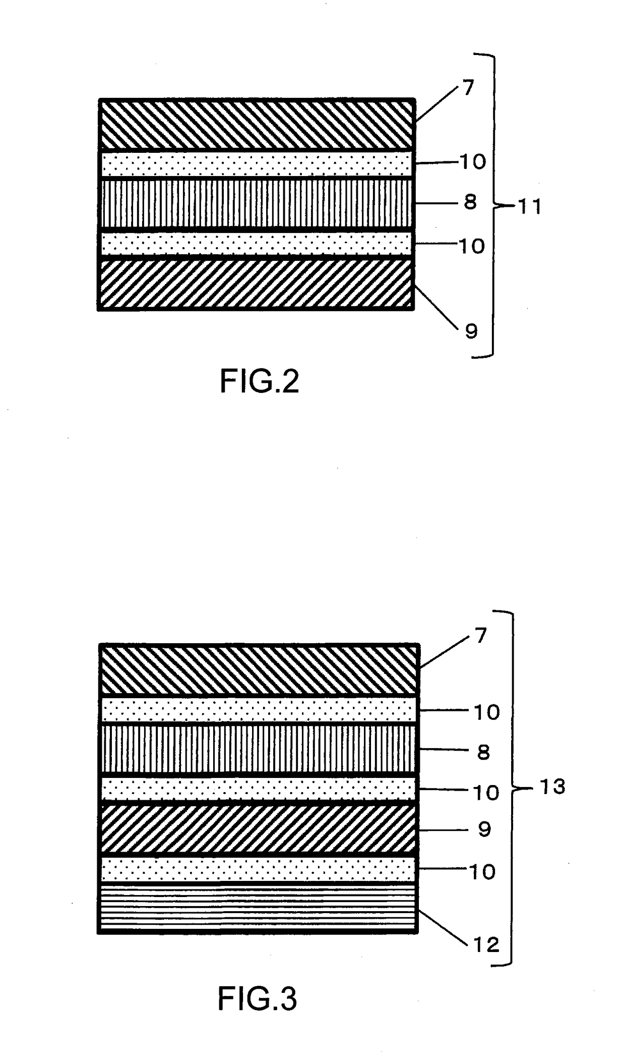
[0120]A light reflecting layer PRL-4 (the coating solution (R4) being used) was obtained on a PET film by a production method similar to Example 1, except that the coating solution (R4) was used. The light reflecting film of the present invention comprising four layers, which are the light reflecting layer PRL-1, the light reflecting layer PRL-2, the light reflecting layer PRL-3, and light reflecting layer PRL-4 laminated in this order, was obtained by: peeling off the PET film at the light reflecting layer PRL-3 side of the light reflecting film obtained by (1) to (5) Example 1; laminating, using acrylic pressure sensitive adhesive, the light reflecting layer side of the light reflecting layer PRL-4 on the PET film and the light reflecting layer side of the light reflecting layer PRL-3 from which the PET film was peeled off with each other; and subsequently, peeling off the PET films at both outer sides of the light reflecting layer PRL-1 and the light reflecting layer PRL-4. that ...

example 3

[0123]At the light reflecting layer PRL-4 side of the light reflecting film obtained in Example 2, a broad band quarter wave plate (manufactured by Teijin Corporation: Pure Ace WR-S) serving as a light controlling layer was bonded with a pressure sensitive adhesive to obtain the light controlling film of the present invention. The optical film of the present invention was obtained by interposing this optical film between two polyvinylbutyral intermediate films by a production method similar to Example 1. Further, with a production method similar to Example 1, the optical film of the present invention was interposed using two glass sheets such that one sheet of quarter wave plate is at a glass side of the vehicle exterior side to form a laminated glass to thus obtain the functional glass of the present invention. The obtained functional glass of the present invention had a visible light transmittance of 72%. Then, a ITUD was manufactured with a production method similar to Example 1,...


PUM


Abstract

A light controlling film comprises a light reflecting film and a light controlling layer that are laminated. The light reflecting film comprises at least two laminated light reflecting layers including at least one of light reflecting layers PRL-1 to PRL-3 that a central reflection wavelength of 400 nm-500 nm, 500 nm-600 nm, and 600 nm-700 nm, respectively, and a reflectance to ordinary light at the central reflection wavelength of 5%-25%. The at least two light reflecting layers have central reflection wavelengths that are different from each other. All of the at least two laminated light reflecting layers have a property of reflecting polarized light having the same orientation. The light controlling layer comprises two quarter wave plates, and the light reflecting film is laminated so as to be interposed between the two quarter wave plates.

Description

TECHNICAL FIELD[0001]The present invention relates to a light reflecting film that is suitable for use in, for example, a head-up display, as well as a light controlling film, an optical film, a functional glass and a head-up display including the light reflecting film.BACKGROUND ART[0002]Navigation systems or head-up displays (hereinafter, also referred to as HUDs) are used as a technique of presenting information to drivers of motor vehicles, aircrafts—etc. HUD is a system that projects an image emitted from an image projection unit, such as a liquid crystal display body (hereinafter, also referred to as an LCD), to, for example, a windshield of a motor vehicle.[0003]FIG. 1 is a schematic diagram showing a HUD. As indicated by an optical path 5, light emitted from an image display units 2 reflects off the reflective mirror 3, reflects off a windshield 4, and thereafter reaches an observer 1. The observer 1 is viewing an image projected on the windshield 4, but the image appears as...

Claims


Application Information

Patent Timeline
IPC IPC(8): G02B5/08B60K35/00G02B5/30G02B27/01G02B5/26
CPCG02B5/0816G02B27/0101G02B5/26G02B5/3083B60K2350/106G02B2027/0118B60K2350/2052B60K2350/2069B60K2350/921B60K35/00B60K2370/152B60K2370/334B60K2370/349B60K2370/77G02B2027/012G02B2027/0194G02B5/08G02B5/30G02B27/01G02F1/1335
Inventor TANAKA, KOUICHITAKAHASHI, CHIHIROYOKOYAMA, YUIHAYASAKI, TOMOYUKI
Owner NIPPON KAYAKU CO LTD
Why Eureka
Try Eureka