System and method for high power pulse generator

a high-power pulse and generator technology, applied in the direction of pulse generation, pulse technique, electric discharge tube, etc., can solve the problems of increasing the complexity and cost of modulators and cabling, reducing the mean time to failure (mttf) of pulse generator, and reducing the complexity of primary energy sources. , the effect of reducing the time that high-voltage is across the solid-state switch

Active Publication Date: 2017-08-17
STANGENES IND INC
View PDF7 Cites 3 Cited by
  • Summary
  • Abstract
  • Description
  • Claims
  • Application Information

AI Technical Summary

Benefits of technology

[0009]Accordingly, a system and method for generating and delivering a high power pulse to a kicker magnet is provided. The system and method can include a circuit configured to store charge in an inductor during a time period when the kicker magnet is not activated. When the kicker is activated, the circuit can be configured such that the charge stored in an inductor is immediately driven into the kicker magnet. The components of the circuit can include protection features such as Zener diodes that ensure that the circuit does not become negatively impacted from anomalies that can be present in the particle-beam high power environment.
[0010]The main susceptibility of pulse generator circuits to radiation-induced failure can be the solid-state switches employed by the circuit that are in an open-state holding off high-voltage. By using an inductively-driven topology to switch DC current flowing through a considerable inductance into the kicker magnet, the time that high-voltage is across the solid-state switch can be minimized and substantially equal to the current rise-time and fall-time in the kicker magnet, thus increasing a mean time to failure (MTTF) of the pulse generator in the radiation environment.
[0011]The complexity of the primary energy source can also be reduced to a low-voltage high-current supply that can be located with the controls away from the radiation and linked by high-current DC cabling. This method can allow for an arbitrary pulse width and rep-rate as well as substantially unlimited DC current in the kicker with minimal droop after the initial fast-rise.

Problems solved by technology

One method to terminate the particle beam is to simply turn it off, however the amount of time needed to turn the beam off can be lengthy, and thus may not prove to be an effective method to remove the beam from impinging upon a target in an emergency situation.
Conventionally, the modulator may be located hundreds of feet away from the radiation environment, increasing the complexity and cost of the modulator and cabling.
Powering up the magnet used to the deflect the beam quickly can be critical due to the fact that during the period of time when the magnetic field is building in the kicker magnet, the beam is only being partially deflected and may begin to impinge on unintended surfaces such as the hardware components associated with the particle beam or other surrounding areas.
Given the amount of current and voltage required to generate a magnetic field with enough of strength to deflect a particle beam, a traditional pulse generator may not be adequate due to the high voltage and currents needed to build the magnetic field.

Method used


Image

  • System and method for high power pulse generator
  • System and method for high power pulse generator
  • System and method for high power pulse generator

Examples


Embodiment Construction

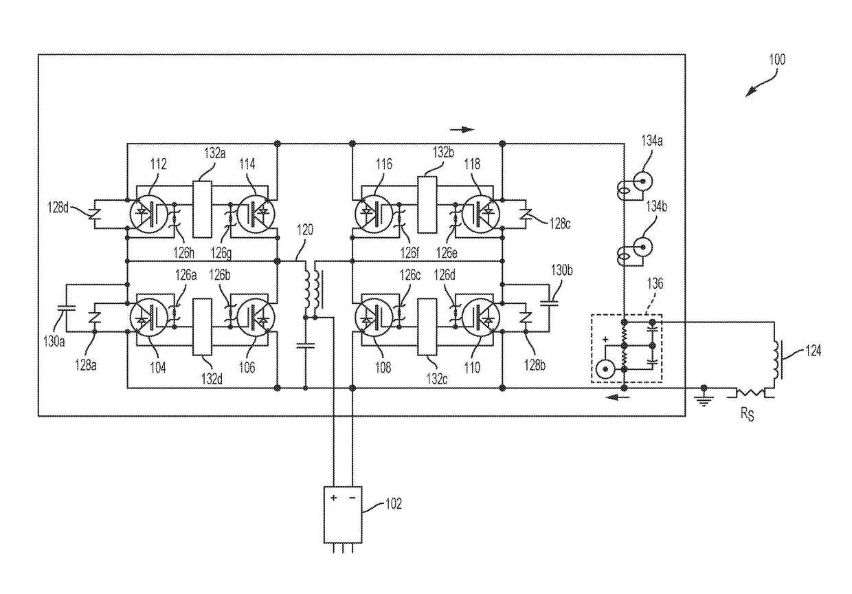
[0015]Described herein are systems and methods for generating high power pulses with fast rise times for use in driving a magnetic load such as that used in a kicker magnet. The systems and methods described herein can be used to ensure that a kicker magnet receives a high powered current pulse with a minimal rise time, when a user of the kicker of the magnet activates the magnet.

[0016]The systems and method employ a circuit that includes a first inductor with a large inductance to build up and store a magnetic field during a time period when the kicker magnet is not being operated. When the kicker magnet is activated, the configuration of the circuit is switched so that the energy stored in the first inductor quickly induces a large voltage across the kicker magnet thereby ensuring that the kicker magnet is activated quickly and with a sufficient current and magnetic field to cause the particle beam to deflect.

[0017]FIG. 1 illustrates an exemplary high power pulse generation circui...


PUM


Abstract

A device and method for generating pulses to activate and deactivate a kicker magnet is provided. When the kicker magnet is deactivated the circuit generates and stores a magnetic field in an inductor. When the kicker magnet is activated, the circuit changes configuration so that the magnetic field and current stored in the inductor can provide the necessary current to activate the kicker magnet is a minimal amount of time. The configuration of the circuit changes via the use of switches. The switches can employ Zener diodes arranged so as to provide protection against high voltage events and rogue neutrinos that may bombard the switches when the kicker magnet is used in the context of deflecting a particle beam.

Description

CROSS-REFERENCE TO RELATED APPLICATION[0001]This application claims priority to U.S. Provisional Application Ser. No. 62 / 295,362, filed Feb. 15, 2016, titled “SYSTEM AND METHOD FOR HIGH POWER PULSE GENERATOR,” which is hereby incorporated by reference in its entirety.FIELD OF THE DISCLOSURE[0002]This disclosure relates to the generation of high power pulses with a minimal rise time for use in powering devices such as a kicker magnet that require high powered pulses to quickly power a magnet designed to deflect a particle beam away from or towards a target.BACKGROUND OF THE DISCLOSURE[0003]Directed particle beams can be used in the research, industry, and medical applications to achieve various benefits. As an example, a directed particle beam can be used to ionize cancerous cells thereby changing the characteristics of the cancerous cells and often times hampering the ability of the cancerous cells to proliferate.[0004]As a safety mechanism, an operator controlling the directed part...

Claims


Application Information

Patent Timeline
Patent Type & Authority Applications(United States)
IPC IPC(8): H01J37/141H03K17/567
CPCH03K17/567H01J37/141H03K3/43H01J2237/1504H05H2007/022H05H2007/046H03K3/45H05H7/04H05H2007/048H05H7/02
Inventor YECKEL, CHRISTOPHERCASSEL, RICHARD
Owner STANGENES IND INC
Why Eureka
Try Eureka