Grid capacitive power storage system

Inactive Publication Date: 2017-08-17
CAPACITOR SCI
View PDF17 Cites 20 Cited by
  • Summary
  • Abstract
  • Description
  • Claims
  • Application Information

AI Technical Summary

Benefits of technology

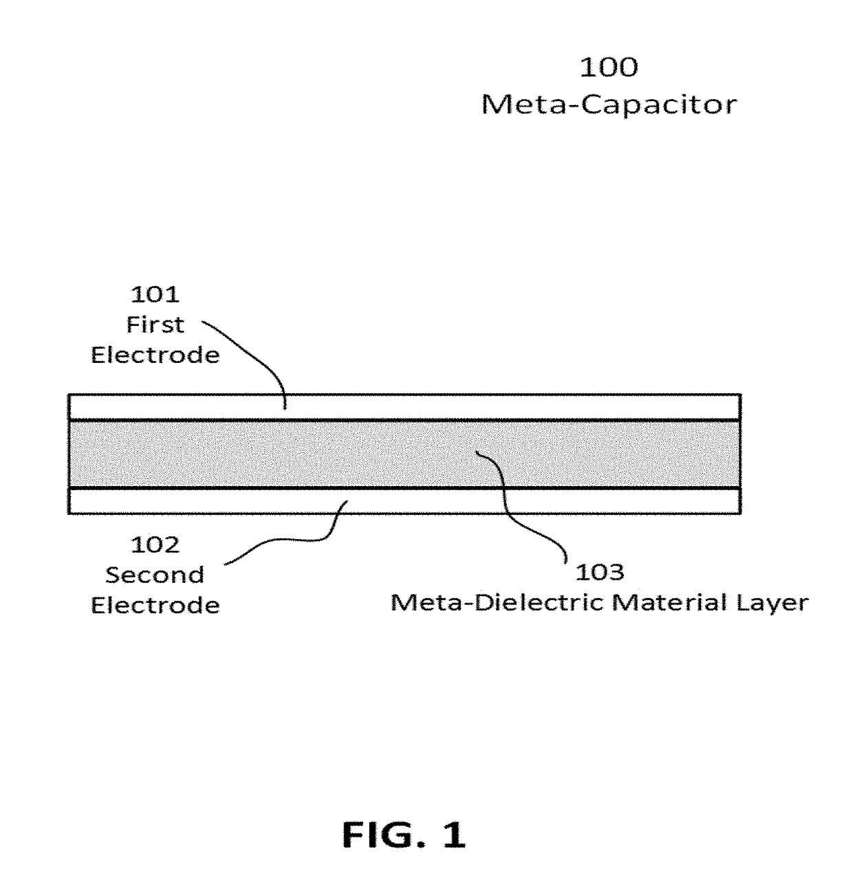
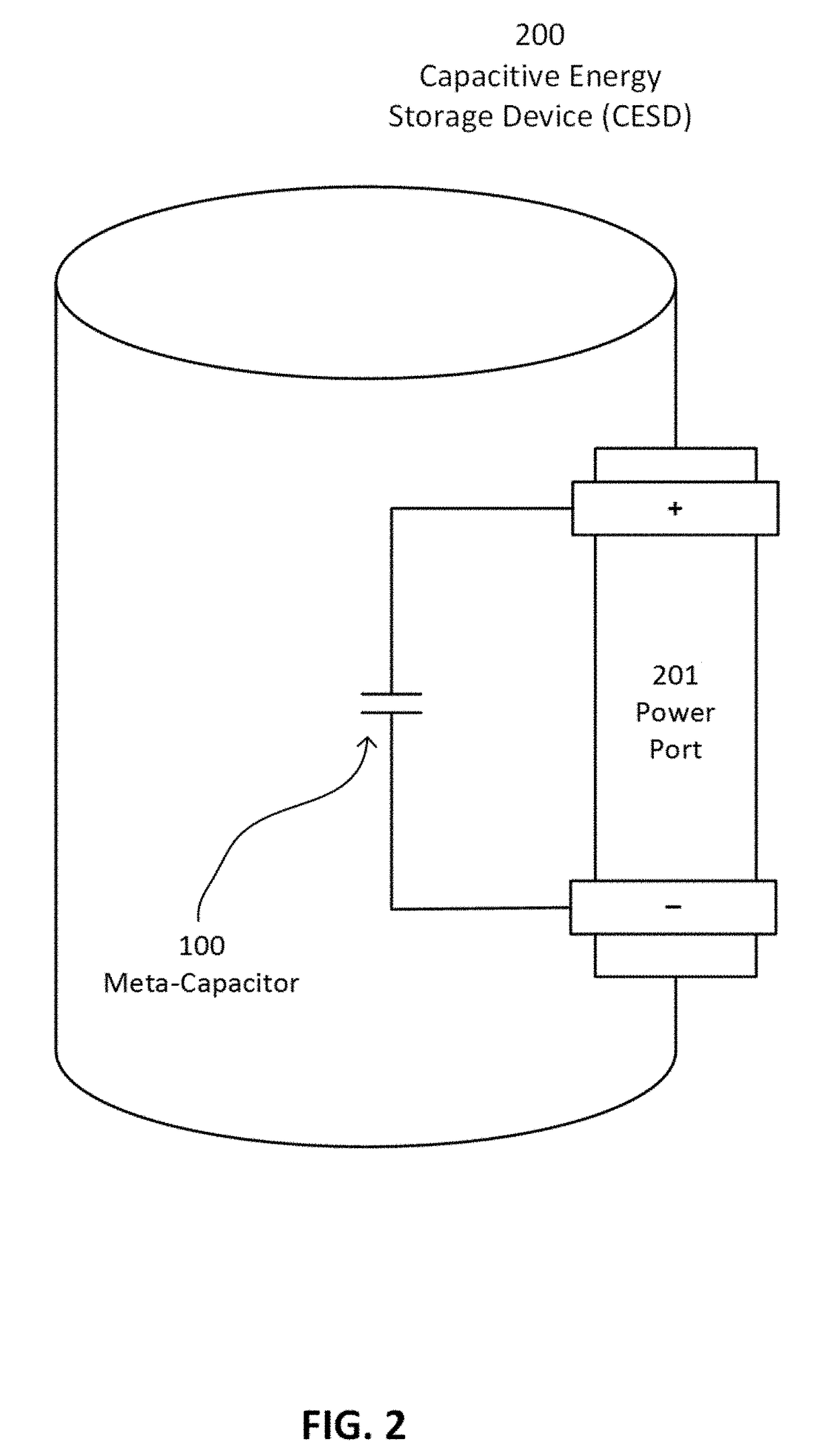
[0018]One major novel aspect of the present invention is the use of at least one meta-capacitor. A meta-capacitor is a dielectric film capacitor whose dielectric film is a meta-dielectric material layer, which is disposed between a first electrode and a second electrode. A meta-dielectric material is described below. Meta-capac

Problems solved by technology

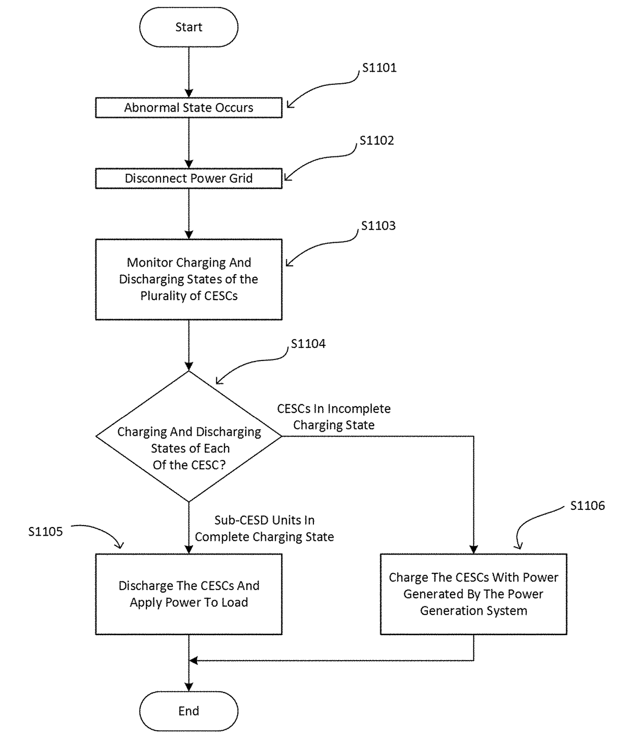
Power generation systems generate power that is transmitted to a power grid, and if the power generation system does not generate sufficient amount of power, the deficient power is supplied from the power grid.
A breakdown of a power generator, a transmission line, or a distribution network can cause a complete or partial power disruption in the normal flow of electricity to the power grid.
In this situation, the ESS performs an uninterruptible power supply (UPS) function and transfers the stored power to the load.
However, the use of rechargeable batteries, such as in Moon, has major drawbacks.
This would make the battery useless in a few weeks.
It will cause severe burns to tissue and corrosion to many metals.
Furthermore, lead-acid batter

Method used


Image

  • Grid capacitive power storage system
  • Grid capacitive power storage system
  • Grid capacitive power storage system

Examples


example 1

[0063]This Example describes synthesis of one type of Sharp polymer according following structural scheme:

[0064]The process involved in the synthesis in this example may be understood in terms of the following five steps.

[0065]a) First Step:

[0066]Anhydride 1 (60.0 g, 0.15 mol, 1.0 eq), amine 2 (114.4 g, 0.34 mol, 2.2 eq) and imidazole (686.0 g, 10.2 mol, 30 eq to 2) were mixed well into a 500 mL of round-bottom flask equipped with a bump-guarder. The mixture was degassed three times, stirred at 160° C. for 3 hr, 180° C. for 3 hr, and cooled to rt. The reaction mixture was crushed into water (1000 mL) with stirring. Precipitate was collected with filtration, washed with water (2×500 mL), methanol (2×300 mL) and dried on high vacuum. The crude product was purified by flash chromatography column (CH2Cl2 / hexane=1 / 1) to give 77.2 g (48.7%) of the desired product 3 as an orange solid. 1H NMR (300 MHz, CDCl3) δ 8.65-8.59 (m, 8H), 5.20-5.16 (m, 2H), 2.29-2.22 (m, 4H), 1.88-1.82 (m, 4H), 1.4...

example 2

[0075]This Example describes synthesis of a Sharp polymer according following structural scheme:

[0076]The process involved in the synthesis in this example may be understood in terms of the following four steps.

[0077]a) First Step:

[0078]To a solution of the ketone 1 (37.0 g, 0.11 mol, 1.0 eq) in methanol (400 mL) was added ammonium acetate (85.3 g, 1.11 mol, 10.0 eq) and NaCNBH3 (28.5 g, 0.44 mol, 4.0 eq) in portions. The mixture was stirred at reflux for 6 hours, cooled to room temperature and concentrated. Sat. NaHCO3 (500 mL) was added to the residue and the mixture was stirred at room temperature for 1 hour. Precipitate was collected by filtration, washed with water (4×100 mL), dried on a high vacuum to give 33.6 g (87%) of the amine 2 as a white solid.

[0079]b) Second Step:

[0080]Mixed well the amine 2 (20.0 g, 58.7 mmol, 2.2 equ), 3,4,9,10-perylenetetracarboxylic dianhydride (10.5 g, 26.7 mmol, 1.0 eq) and imidazole (54.6 g, 0.80 mmol, 30 eq to diamine) into a 250 mL round-botto...

example 3

[0097]Carboxylic acid co-polymer P002. To a solution of 1.02 g (11.81 mmol) of methacrylic acid and 4.00 g (11.81 mmol) of stearylmethacrylate in 2.0 g isopropanol was added a solution of 0.030 g 2,2′-azobis(2-methylpropionitrile) (AIBN) in 5.0 g of toluene. The resulting solution was heated to 80 C for 20 hours in a sealed vial, after which it became noticeably viscous. NMR shows <2% remaining monomer. The solution was used without further purification in film formulations and other mixtures.


PUM


Abstract

A capacitor based energy storage system (CBESS) and methods of using it are disclosed. The CBESS uses meta-capacitors in its capacitive energy storage devices (CESD) to configure capacitive energy storage cells (CESC), which are used to configure capacitive energy storage modules (CESM) to achieve the CBESS's function as an uninterruptible power supply. The CBESS is connected to a power generation system (PGS), a load, and a power grid. When the grid is in an abnormal state, the CESM is simultaneously charged with power from the PGS and used to supply power to the load. If a remaining amount of power of a CESM is less than a predetermined level, the CESM is charged with power from PGS or grid. The CBESS interfaces with a computer system or network to buy or sell electricity to the grid depending on grid electricity cost and CESD charging states.

Description

CROSS-REFERENCE TO RELATED APPLICATIONS[0001]This application claims the priority benefit of U.S. Provisional Patent Application, No. 62 / 294,964, filed on 12 Feb. 2016, in the USPTO, the entire disclosures of which are incorporated herein by reference. This application is a continuation-in-part of U.S. patent applications Ser. Nos. 15 / 043,315, 15 / 043,186, 15 / 043,209, and 15 / 043,247, all of which were filed Feb. 12, 2016, the entire contents of all of which are incorporated herein by reference.BACKGROUND OF THE DISCLOSURE[0002]1. Field of the Invention[0003]This present disclosure relates to a power storage system for supplying power to a load or a power grid in association with a power generation system and a power grid. Additionally, this invention relates to a method of operating a power storage system to supply power to a load or a power grid in association with a power generation system and a power grid. Unlike conventional power storage systems that are based on batteries, the ...

Claims


Application Information

Patent Timeline
IPC IPC(8): H02J7/00H02M7/68H02J7/34
CPCH02J7/0045H02J7/0026H02M7/68H02J7/345H02J7/007H02J3/28H02J7/0018H02J15/008
Inventor LAZAREV, PAVEL IVANKELLY-MORGAN, IAN S.G.ROBINSON, MATHEW R.
Owner CAPACITOR SCI
Why Eureka
Try Eureka