
Eureka
For R&D, Eureka makes reading and utilizing patents & technical documents easy.
Eureka AIR
Designed for self-driven R&D workflows. Generate viable solutions, solve complex R&D challenges, empower your innovation with AI.

Eureka Materials
Designed for material experts only. Revolutionize your material R&D, from search, analyze, to developing new materials.

TechResearch
Generate reliable direction feasibility study reports for your R&D in just a few steps.

TechSeek
Discover and master advanced knowledge NOW. Basics, ideas, possibilities, all at once.

TechMind
As an expert in R&D Theories, TechMind can generates customized viable solutions instantly.

TechRisk
Analyze your overall solution with one click, know your potential R&D risks in advance.

TechMonitor
Get weekly tech updates, stay abreast of the latest tech innovations and key insights.
Photoelectrode, method for manufacturing same, and photoelectrochemical cell
- Summary
- Abstract
- Description
- Claims
- Application Information
AI Technical Summary
Benefits of technology
Problems solved by technology
Method used
Image

Examples
first exemplary embodiment
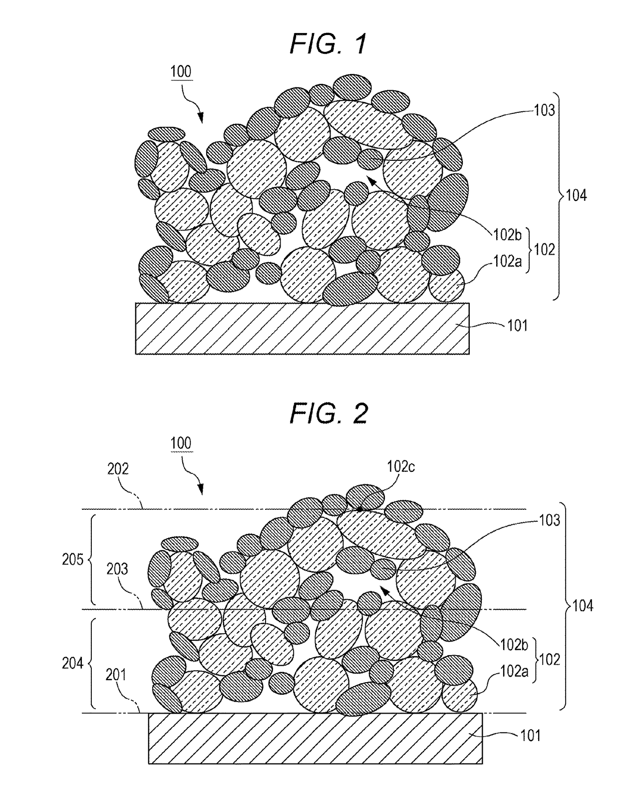
[0055]A photoelectrode of a first exemplary embodiment includes a first conductor as a substrate, and a second conductor disposed on the first conductor. The second conductor has a porous structure including a three-dimensionally continuous skeleton and pores formed by the skeleton, and is transparent. The photoelectrode of this exemplary embodiment further includes a visible-light photocatalyst disposed in the pores of the second conductor. The visible-light photocatalyst should be disposed at least in the pores of the second conductor, and may be disposed further on a surface of the second conductor. The visible-light photocatalyst may be in the form of particles, or in the form of a film. It can be considered that a photocatalyst layer including a visible-light photocatalyst is disposed in the pores of the second conductor in the photoelectrode of this exemplary embodiment.
[0056]The phrase “the skeleton of the second conductor is three-dimensionally continuous” encompasses not on...
second exemplary embodiment
[0080]One exemplary embodiment of a photoelectrochemical cell of the present disclosure will be described.
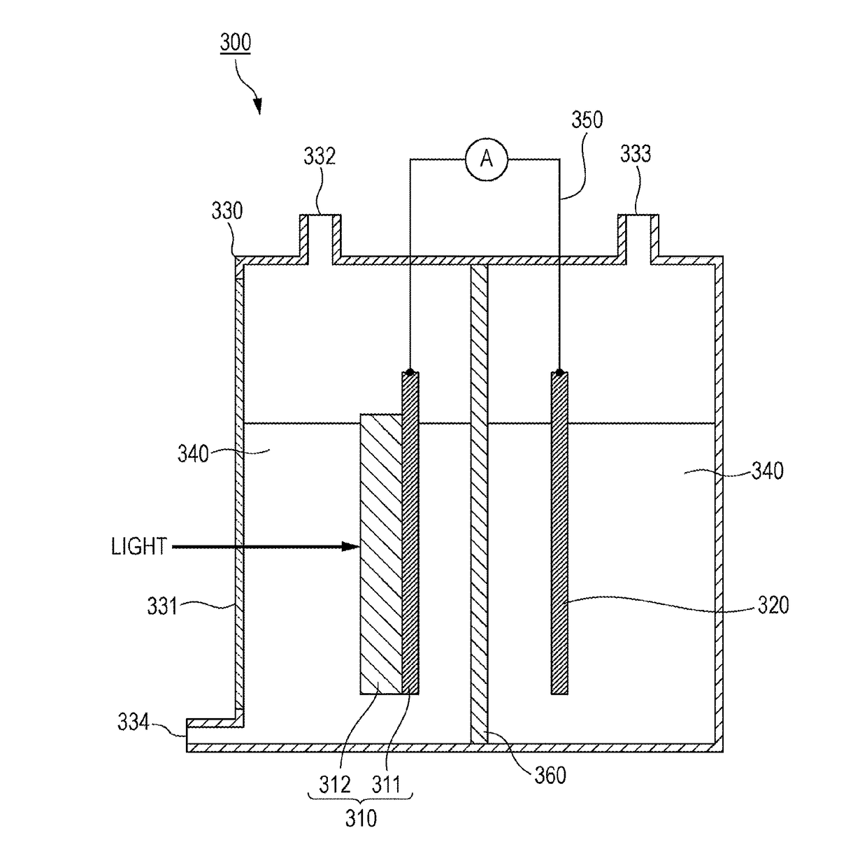
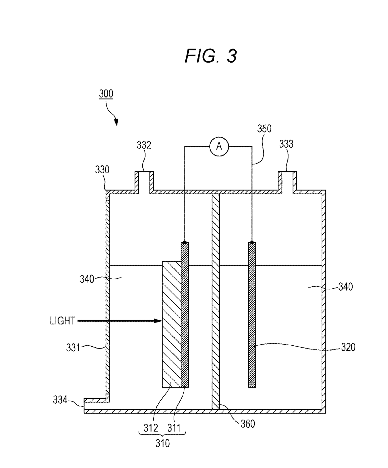
[0081]FIG. 3 shows one example of the photoelectrochemical cell of this exemplary embodiment. Photoelectrochemical cell 300 shown in FIG. 3 includes photoelectrode 310; counter electrode 320; electrolytic solution 340 containing water; and container 330 that stores photoelectrode 310, counter electrode 320, and electrolytic solution 340.
[0082]As photoelectrode 310, the photoelectrode described in the first exemplary embodiment is used. Photoelectrode 310 includes first conductor 311 as a substrate, and composite 312 disposed on first conductor 311 and composed of a second conductor and a visible-light photocatalyst. The second conductor has a porous structure including a three-dimensionally continuous skeleton and pores formed by the skeleton, and is transparent as described in the first exemplary embodiment. The visible-light photocatalyst is disposed in the pores of the second...
example 1
[0096](1) Step of Forming Second Conductor (Antimony-Doped Tin Oxide: ATO)
[0097]An ATO substrate was provided as a first conductor. An ATO powder having a primary particle size of 120 nm to 250 nm was used as a transparent conductive oxide for producing a second conductor. An ink with the ATO powder dispersed in an organic solvent was prepared, deposited on the ATO substrate by spin coating, and dried for about 5 minutes on a hot plate set at 120° C. Conditions for spin coating included rotation at a rotation number of 400 rpm for 20 seconds, followed by rotation at a rotation number of 1500 rpm for 10 seconds. After the drying, the film on the ATO substrate was fired in a mixed gas stream of oxygen and nitrogen. In the firing, a temperature in a furnace was elevated from room temperature to 500° C. at a temperature elevation rate of 100° C. / h, held at 500° C. for 1 hour, and then lowered at a temperature falling rate of 100° C. / h, and the film was taken out from the furnace at the ...
PUM
 Abstract
Description
Claims
Application Information
 - R&D Engineer
- R&D Manager
- IP Professional
- Industry Leading Data Capabilities
- Powerful AI technology
- Patent DNA Extraction
Browse by: Latest US Patents, China's latest patents, Technical Efficacy Thesaurus, Application Domain, Technology Topic, Popular Technical Reports.
© 2024 PatSnap. All rights reserved.Legal|Privacy policy|Modern Slavery Act Transparency Statement|Sitemap|About US| Contact US: help@patsnap.com