Production method for fiber-reinforced thermoplastic resin composite material, production method for fiber-reinforced thermoplastic resin tape, production method for press-molding material, production method for molded article, unidirectional prepreg, and molded article

a thermoplastic resin and composite material technology, applied in the direction of coatings, etc., can solve the problems of high production cost, high production cost, and high cost, and achieve the effects of improving productivity, reducing shear stress, and increasing line speed

Pending Publication Date: 2017-09-14
MITSUBISHI CHEM CORP
View PDF4 Cites 4 Cited by
  • Summary
  • Abstract
  • Description
  • Claims
  • Application Information

AI Technical Summary

Benefits of technology

[0047]It is possible to decrease the shear stress as compared to a die having a narrow slit since it is possible to use a crosshead die having a high opening height, and it is thus possible to increase the line speed and to improve the productivity. Furthermore, it is less concerned that the fiber is broken due to clogging of fluff since the crosshead die does not have a narrow slit portion, the restoration in the case of breakage is also easy, and it is thus possible to decrease the production loss. In addition, it is easy to release the composite material from the pressurizing device and it is possible to increase the speed since the composite material is pressurized while being cooled in this production method.

Problems solved by technology

In this method, the carbon fibers are required to be highly aligned in one direction, and it is thus concerned that a problem of fluffs derived from the carbon fiber and the like is caused and it is difficult to improve the line speed.
Hence, it is concerned that there is a problem in securing reliability when being used in practical members.
The pressure applied to the slit nozzle is likely to increase when the slit nozzles interval is narrow and it is thus concerned that it is difficult to improve the line speed.
In this method, although it is possible to achieve an increase in speed of the process of forming a sheet, the tape-like towpreg is highly impregnated when being produced and it is thus difficult to achieve an increase in speed.
However, in this method, the attached product passes between rolls at 250° C. of a higher temperature than the melting point of nylon 6, and it is thus considered that it is not easy to release the attached product.
However, in this method, not only the fiber-reinforced thermoplastic resin but also the plate-like material to heat and cool this is required to be repeatedly heated and cooled, and it is thus difficult to achieve an increase in speed.

Method used


Image

  • Production method for fiber-reinforced thermoplastic resin composite material, production method for fiber-reinforced thermoplastic resin tape, production method for press-molding material, production method for molded article, unidirectional prepreg, and molded article
  • Production method for fiber-reinforced thermoplastic resin composite material, production method for fiber-reinforced thermoplastic resin tape, production method for press-molding material, production method for molded article, unidirectional prepreg, and molded article
  • Production method for fiber-reinforced thermoplastic resin composite material, production method for fiber-reinforced thermoplastic resin tape, production method for press-molding material, production method for molded article, unidirectional prepreg, and molded article

Examples


example 1

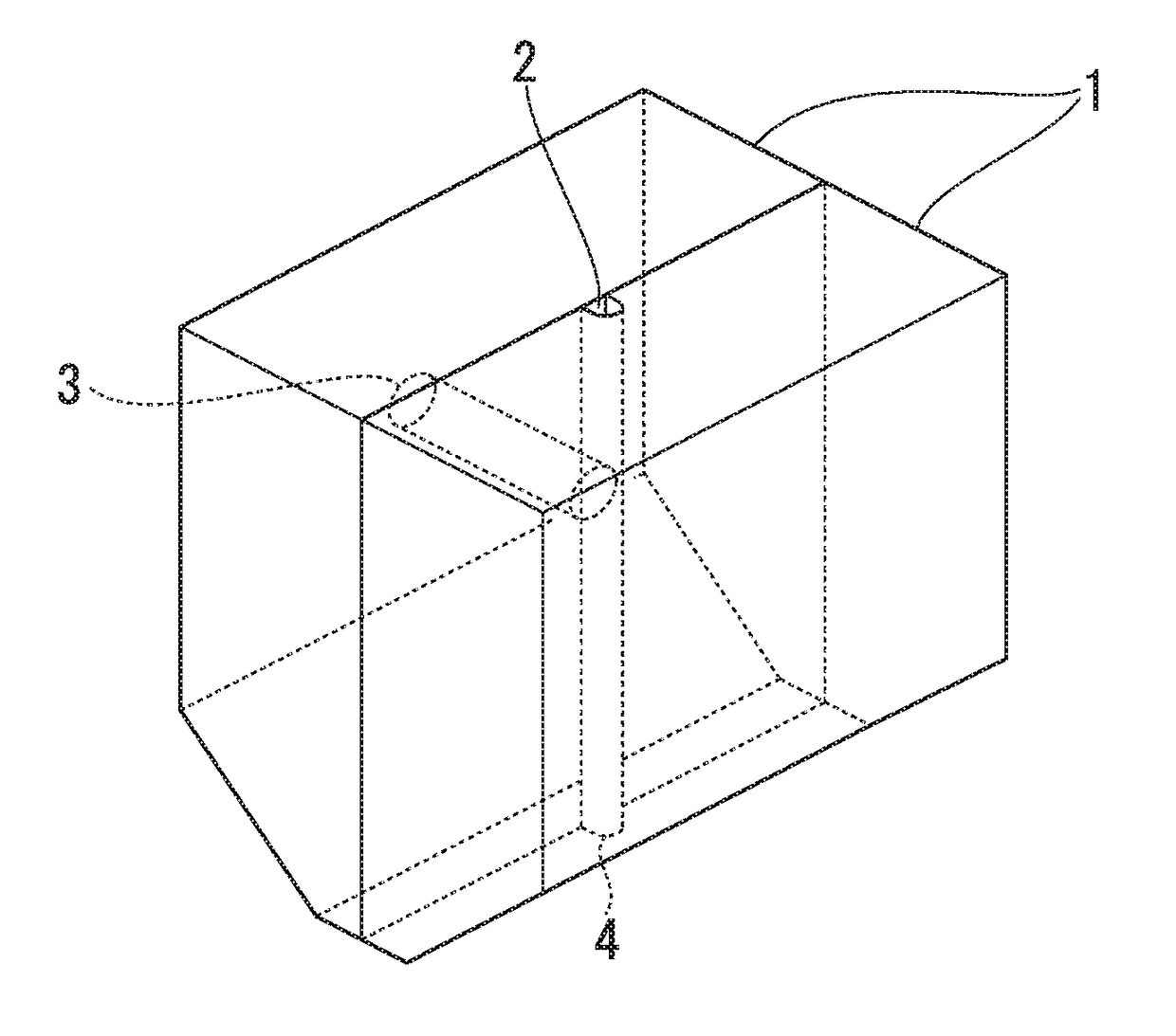
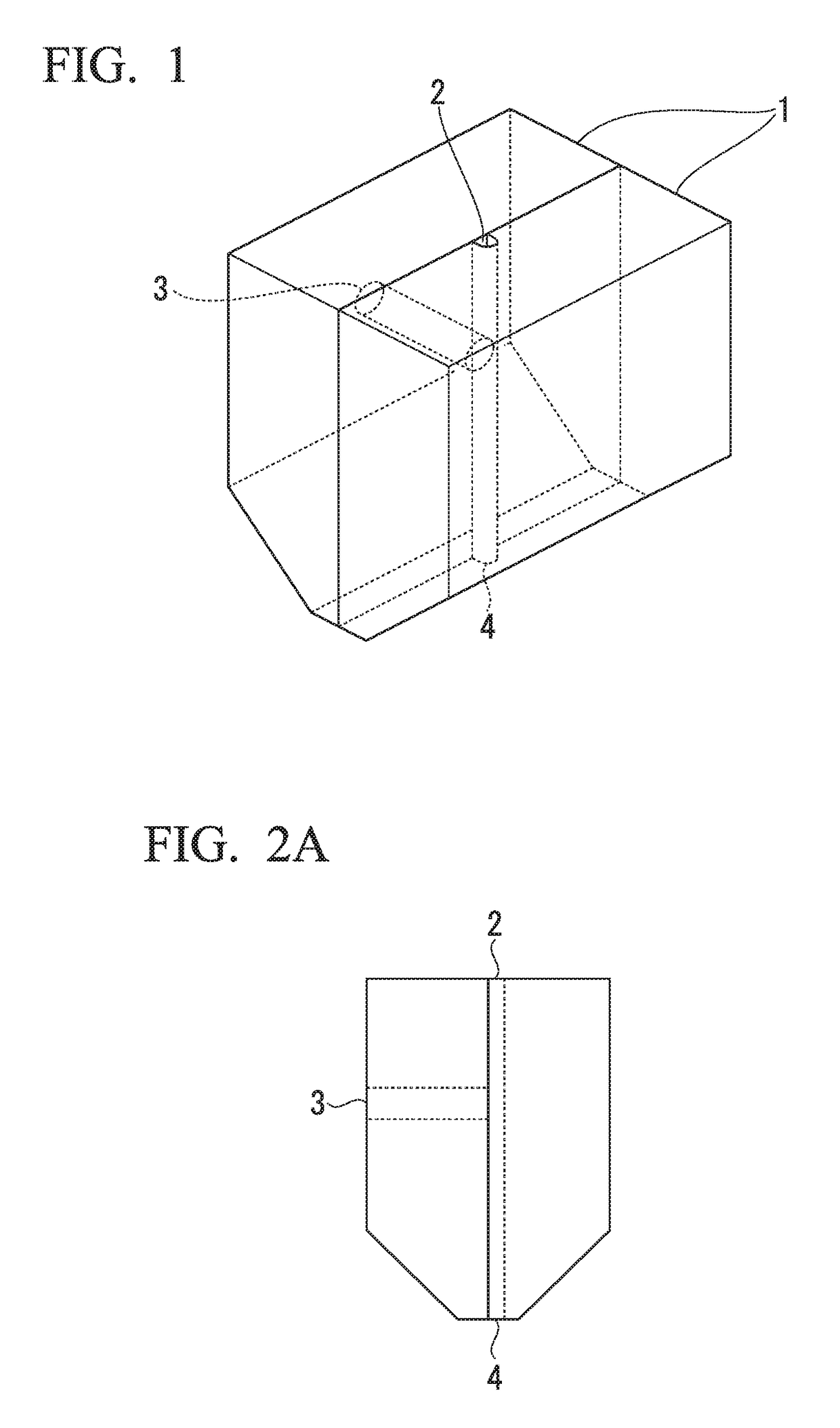
[0138]The nylon resin (A-1) was supplied to a 30φ twin screw extruder at a rate of 0.83 kg / h by using a metering feeder, plasticized at 250° C., supplied to a vertical wire coating die set at 280° C., and composited with the carbon fiber (B). The die outlet (outlet opening 4) has a height of 2.5 mm and a width of 2.5 mm, and the die is one for one having a shape in which a semicircle having a height of 1.25 mm, a width of 2.5 mm, and a diameter of 2.5 mm and a rectangle having a height of 1.25 mm and a width of 2.5 mm are combined in the height direction.

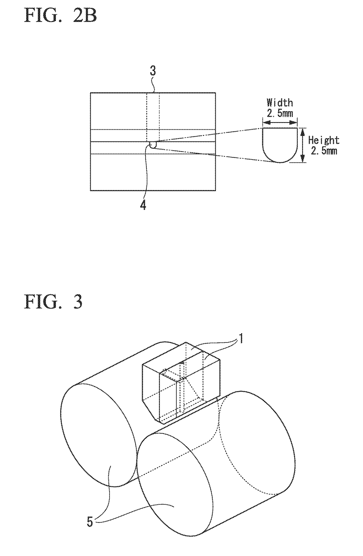
[0139]The composite strand was allowed to pass between the two metal pressure rolls 5 which had a diameter of 100 mm and in which water at 30° C. was circulated to be crushed. The pressurizing force of the pressure roll 5 was adjusted to 31 kgf. The pressure roll was installed immediately below the die outlet (outlet opening), and the position thereof was adjusted so that upper 40 mm of the center of the two pressure rolls became th...

example 2

[0141]Example 2 was carried out in the same manner as in Example 1 except that the pressurizing force was adjusted to 5 kgf. The thickness of the tape thus obtained was 0.4 mm, the fiber was expanded in the width direction in the tape, and the surface thereof was covered with the resin.

example 3

[0142]Example 3 was carried out in the same manner as in Example 1 except that the quantity of the nylon resin supplied was set to 2.23 kg / h. The ratio of carbon fiber calculated from the charged quantity is 35%. The thickness of the tape thus obtained was 0.2 mm, the fiber was expanded in the width direction in the tape, and the surface thereof was covered with the resin.


PUM

PropertyMeasurementUnit
heightaaaaaaaaaa
thicknessaaaaaaaaaa
thicknessaaaaaaaaaa

Abstract

A production method for a fiber-reinforced thermoplastic resin composite material, the method using a crosshead die (1) that has a maximum aperture height of 1 mm or more, wherein reinforcing fibers are supplied in a reinforcing fiber bundle to the crosshead die (1), the reinforcing fibers are conjugated with a melted thermoplastic resin, and the conjugate is brought into contact with a pressurization surface that is at or below the solidification temperature of the thermoplastic resin, is pressurized, and is shaped to have a thickness that is 50% or less of the aperture height.

Description

TECHNICAL FIELD[0001]The present invention relates to a production method for a fiber-reinforced thermoplastic resin composite material, a production method for a fiber-reinforced thermoplastic resin tape, a production method for a press-molding material, a production method for a molded article, a unidirectional prepreg, and a molded article.[0002]This application is based upon and claims the benefit of priority of the prior Japanese Patent Application No. 2014-188705 filed in Japan on Sep. 17, 2014 and the prior Japanese Patent Application No. 2015-047983 filed in Japan on Mar. 11, 2015, the entire contents of which are incorporated herein by reference.BACKGROUND ART[0003]Carbon fibers and carbon fiber composite materials have excellent features such as a high tensile strength and a high tensile modulus of elasticity, excellent heat resistance, chemical resistance, fatigue characteristics, and wear and abrasion resistance, a low coefficient of linear expansion, excellent dimension...

Claims


Application Information

Patent Timeline
Patent Type & Authority Applications(United States)
IPC IPC(8): B29B11/16B29C70/50B29C48/04B29C48/05B29C48/12
CPCB29B11/16B29C70/50B29K2105/0881B29K2307/04B29K2101/12B29C43/22B29B7/90B29B9/06B29B9/14B29B15/122B29C48/92B29C48/0011B29C48/16B29C48/35B29C2948/92523B29C48/04B29C48/05B29C48/12
Inventor OKUNAKA, OSAMU
Owner MITSUBISHI CHEM CORP
Why Eureka
Try Eureka