System and method for plasma-mediated modification of tissue

Active Publication Date: 2017-09-21
AMO DEVMENT
View PDF5 Cites 3 Cited by
  • Summary
  • Abstract
  • Description
  • Claims
  • Application Information

AI Technical Summary

Benefits of technology

[0007]One embodiment is directed to a system for cataract surgery on an eye of a patient, comprising: a first laser source configured to deliver a first laser beam in a pulsed form at a first pulse energy; a second laser source configured to deliver a second laser beam in a pulsed form at a second pulse energy greater than the first pulse energy; an scanning optical system, configured to: receive the first and second laser beams; and adjust a first focus position of the first laser beam, and a second focus position of the second laser beam, in up to three dimensions to direct the first and second laser beams onto one or more targeted tissue structure portions of the eye of the patient; a controller operatively coupled to the scanning optical system and configured to cause the scanning optical system to adjust the first focus position to photodisrupt a first tissue structure portion with the first laser beam, and subsequently adjust the second focus position to further photodisrupt the first tissue structure portion with the second laser beam. The first pulse energy may be between about one-half microjoule and about 50 microjoules. The second pulse energy may be between about 50 microjoules and about 5,000 microjoules. The first laser source may be configured to produce laser pulses having a first pulse duration between about 100 femtoseconds and about 10 picoseconds. The second laser source may be configured to produce laser pulses having a second pulse duration between about 10 picoseconds and about 10 nanoseconds. The controller may be configured to control the optical system to direct the first and second laser beams based upon a predetermined treatment pattern. The first tissue structure portion may be a portion of a crystalline lens of the eye. The controller may be operatively coupled to the first and seco

Problems solved by technology

These are the longest and thought to be the most dangerous step in the procedure due to the mechanical manipulation and the use of pulses of ultrasound that may lead to inadvertent ruptures of the posterior lens capsule, posterior disl

Method used


Image

  • System and method for plasma-mediated modification of tissue
  • System and method for plasma-mediated modification of tissue
  • System and method for plasma-mediated modification of tissue

Examples


Example

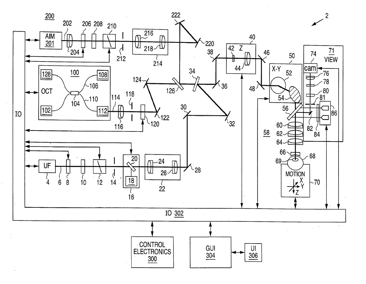
[0034]The present invention can be implemented by a system that projects or scans an optical beam into a patient's eye 68, such as system 2 shown in FIG. 1 which includes an ultrafast (UF) light source 4 (e.g. a femtosecond laser, or a dual purpose system capable of emitting pulses in a lower and in a higher range of pulse energies, perhaps with different pulse durations.). Using this system, a beam may be scanned in a patient's eye in three dimensions: X, Y, Z. In this embodiment, the UF wavelength can vary between 1010 nm to 1100 nm and the pulse width can vary from 100 fs to 10000 fs. The pulse repetition frequency can also vary from 10 kHz to 250 kHz. Safety limits with regard to unintended damage to non-targeted tissue bound the upper limit with regard to repetition rate and pulse energy; while threshold energy, time to complete the procedure and stability bound the lower limit for pulse energy and repetition rate. The peak power of the focused spot in the eye 68 and specifical...


PUM


Abstract

A method for cataract surgery on an eye of a patient includes scanning a first focus position of a first pulsed laser beam at a first pulse energy in a first scanning pattern to photodisrupt a tissue structure of a lens with a plurality of pulses of the first laser beam to form one or more cuts within the lens, the cuts being short of reaching a side edge of the lens and being configured to divide the lens into two or more segments which are attached to each other in regions adjacent the side edge of the lens; and afterwards, completely separating the two or more segments of the lens from each other by scanning a second focus position of a second pulsed laser beam having a second pulse energy higher than the first pulse energy in a second scanning pattern that is co-registered to the first scanning pattern.

Description

RELATED APPLICATION DATA[0001]The present application claims the benefit under 35 U.S.C. §119 to U.S. provisional patent application Ser. No. 61 / 302,437, filed Feb. 8, 2010. The foregoing application is hereby incorporated by reference into the present application in its entirety.FIELD[0002]The present invention relates to ophthalmic surgical procedures and systems, especially cataract surgery of the crystalline lens.BACKGROUND[0003]Cataract extraction is one of the most commonly performed surgical procedures in the world with estimated 2.5 million cases performed annually in the United States and 9.1 million cases worldwide in 2000. This was expected to increase to approximately 13.3 million estimated global cases in 2006. This market is composed of various segments including intraocular lenses for implantation, viscoelastic polymers to facilitate surgical maneuvers, disposable instrumentation including ultrasonic phacoemulsification tips, tubing, and various knives and forceps. Mo...

Claims


Application Information

Patent Timeline
IPC IPC(8): A61F9/008
CPCA61F9/00825A61F2009/00887A61F2009/00897A61F9/00834A61F2009/00851A61F2009/0087A61F9/008
Inventor FRIEDMAN, NEILSEIBEL, BARRYCULBERTSON, WILLIAMSCHUELE, GEORGANDERSEN, DAN
Owner AMO DEVMENT
Why Eureka
Try Eureka