Robot apparatus, control method of robot apparatus, and recording medium

a robot and control method technology, applied in the direction of programmed manipulators, programme control, instruments, etc., can solve the problems of not meeting the precision requirements, the robot apparatus is not frequently used, and the current articulated robot's precision of force (torque control is not achieved, so as to achieve precise force (torque control

Active Publication Date: 2017-09-21
CANON KK
View PDF5 Cites 12 Cited by
  • Summary
  • Abstract
  • Description
  • Claims
  • Application Information

AI Technical Summary

Benefits of technology

[0018]In view of this, an object of the present disclosure is to perform, in a general articulated robot apparatus, satisfactorily precise force (torque) control in which reaction force of a wire rod is considered and perform efficient high-mix low-volume production in a short period without using a dedicated apparatus.

Problems solved by technology

Meanwhile, the robot apparatus is not frequently used in assembly of a smaller load in which a load applied to a component at the time of assembly is approximately several grams, such as operation of a minute component, a film, or a sheet having a weight of several grams.
A reason for this is that precision of force (torque) control of a current articulated robot is not so high and does not achieve required precision needed to perform assembly in which a range of a load applied to a component by an end effector provided at a tip end of a robot arm is approximately several grams.
However, reaction force generated due to deformation of the wire rod for communicating a drive signal to the above joint (or end effector), the deformation being caused by operation of the robot apparatus, influences a measurement value of the torque sensor provided in the joint as a measurement error.
Therefore, in a case where force (or torque) control is performed at the precision of several grams, such reaction force is extremely large disturbance and influences precision of control.
However, Japanese Patent Laid-Open No. 2012-218104 cited above cannot accurately estimate a torque generated in a joint of a robot apparatus because of the following two problems.
The first problem is that, in Japanese Patent Laid-Open No. 2012-218104, an estimation error is generated because the torque generated in the joint is calculated by reverse kinematic operation based on a structure condition such as geometry of the robot or a weight of each part thereof.
In a case where a position of a center of gravity and a value of the weight used in the reverse kinematic operation are different from those of an actual robot apparatus, an estimation error is naturally generated.
Meanwhile, in a case where force of 1 g is controlled at a tip end of a link having 300 mm, it is necessary to control a torque of 3 mNm (300 mm×1 g) in a joint at a root of the link, and an error is more than ten times as much as a control amount and therefore there is a possibility that required precision of assembly cannot be satisfied.
Further, in an actual robot arm, wire rods are not necessarily provided in a state equal to an advance measurement state.
Because of this placement precision problem, in the technique of Japanese Patent Laid-Open No. 2012-218104 using force (torque) estimation calculation, the same reaction force is not necessarily generated actually even in a case where the same joint operation as joint operation in advance measurement is performed.
The second problem is that the table for use in estimation calculation in Japanese Patent Laid-Open No. 2012-218104 is configured only by a static elastic relationship between a joint angle and reaction force of a cable.
Such a viscous change in the cable reaction force related to the deformation speed and such a non-linear (hysteresis) change generated when the cable is deformed / deformation thereof is restored are not considered in Japanese Patent Laid-Open No. 2012-218104, and therefore it is impossible to precisely predict the reaction force of the cable.
Therefore, in the technique of Japanese Patent Laid-Open No. 2012-218104, there is a possibility that, although control is performed in consideration of the reaction force of the wire rod, force (torque) control cannot be performed with satisfactory precision.
However, in a case where a component having a minute weight of several grams is assembled by force control, it is impossible to ignore reduction in the force controllability caused by reaction force of the cable.
However, in particular, in force (torque) control of order of several grams as described above, satisfactory precision cannot be achieved even by the technique in Japanese Patent Laid-Open No. 2012-218104, and the force controllability may be reduced.
The above problems are reasons why a general articulated robot apparatus has not been conventionally used willingly for assembling a minute load.
In addition, a circumstance in which the above dedicated apparatus is individually necessary for each minute (tiny) component can be a serious bottleneck in realization of high-mix low-volume production.
In a case where it is necessary to design and produce the above dedicated apparatus for each of a large number of minute (tiny) components necessary for high-mix low-volume production, there may arise problems such as an increase in a startup period of a production line and a rise in a startup cost because of this.

Method used


Image

  • Robot apparatus, control method of robot apparatus, and recording medium
  • Robot apparatus, control method of robot apparatus, and recording medium
  • Robot apparatus, control method of robot apparatus, and recording medium

Examples


example 1

>

(Basic Configuration of Robot Apparatus)

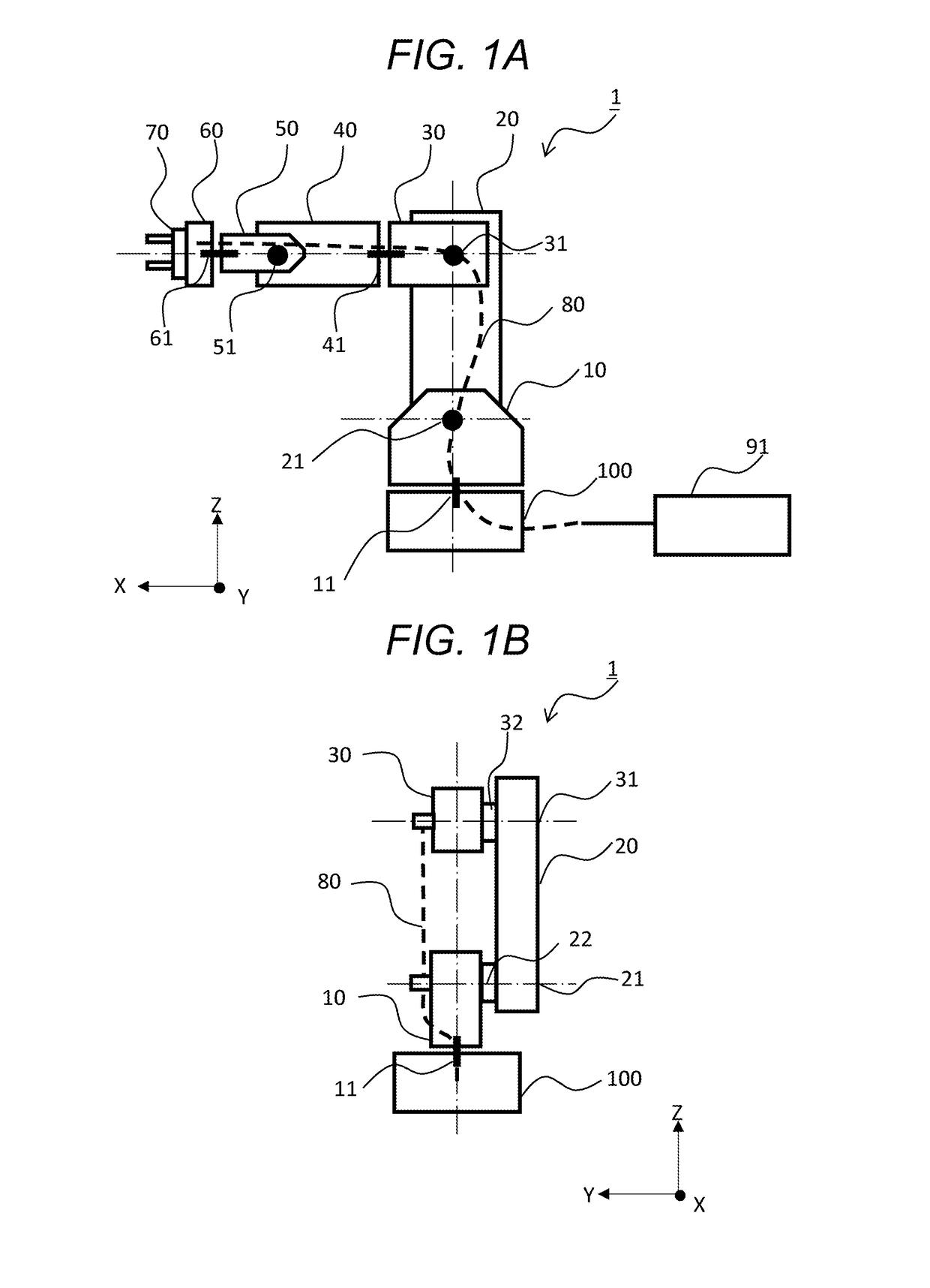
[0035]FIGS. 1A and 1B show the whole configuration of an articulated robot apparatus as an example of a robot apparatus in which the present disclosure is employed. FIG. 1A shows the robot apparatus in this example seen from, for example, a side thereof. Axes of coordinates of a three-dimensional (XYZ) coordinate system used for controlling this robot apparatus are shown in a lower left part of FIG. 1A. As shown in FIG. 1A, among those axes of coordinates, the Z-axis is directed to an upper side of the drawing and the X-axis is directed to a left side of the drawing. FIG. 1B shows a robot arm 1 of the same robot apparatus seen from, for example, a back side thereof (right side in FIG. 1A). Axes of coordinates of a similar three-dimensional (XYZ) coordinate system are also shown in a lower right part of FIG. 1B. For example, a posture of the robot arm 1 shown in FIG. 1A is set as an initial posture.

[0036]As shown in FIG. 1A, the robot apparatu...

example 2

[0130]In this example, some examples of a robot control procedure (robot control program) executable in the CPU 601 of the above control device 91 will be exemplified. FIG. 5 and FIG. 6 show flows of the robot control procedure (robot control program) executable in the CPU 601 of the control device 91.

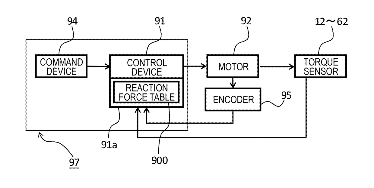
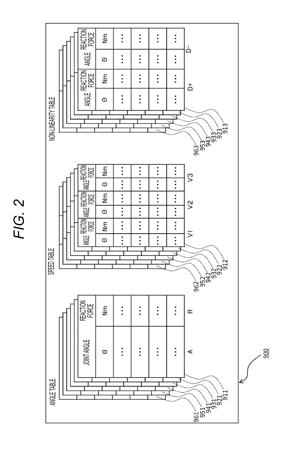
[0131]The control example in FIG. 5 is an example where a command value from the command device 94 for driving a rotary joint is corrected in accordance with cable reaction force shown in the reaction force table 900. Further, the control example in FIG. 6 is an example where torque control is performed by correcting output values of the torque sensors 12, 22, 32, 42, 52, and 62 of the respective rotary joints in accordance with the cable reaction force shown in the reaction force table 900. In order to facilitate understanding, control shown in FIG. 5 and FIG. 6 is simplified as control related to a single specified rotary joint. The control shown in FIG. 5 and FIG. 6 can be stored on...


PUM


Abstract

A robot arm includes a plurality of links and rotary joints for connecting the links with each other. A cable (wire rod) for communicating a drive signal to a drive actuator of each rotary joint is provided along each link. A reaction force table storing a reaction force value generated by the wire rod when the joint is driven in a divided storage area divided for each dynamic drive control condition is provided in a control system. In a case where each rotary joint is driven, the control device controls each rotary joint on the basis of a reaction force value obtained by referring to the reaction force table in accordance with the drive control condition.

Description

BACKGROUND[0001]Field of the Disclosure[0002]The present disclosure relates to a robot apparatus in which a wire rod for communicating drive signals or control signals to parts of a robot arm is provided along a plurality of links constituting the robot arm, relates to a control method thereof, and relates to a recording medium.[0003]Description of the Related Art[0004]In recent years, as a robot apparatus such as a multi-axis articulated robot having joints whose rotation is restricted, an articulated robot in which a torque sensor for measuring a torque that a drive actuator applies to a link is provided in a joint to perform torque (force) control of a torque generated in the joint has drawn attention. Because the torque sensor is provided in the joint, it is easy to control force generated in the joint of the articulated robot and control a load or force that an end effector provided at a tip end of the robot arm applies to a component.[0005]At present, a robot apparatus includi...

Claims


Application Information

Patent Timeline
Patent Type & Authority Applications(United States)
IPC IPC(8): B25J9/16B25J13/08
CPCB25J9/1687B25J13/085G05B2219/45064Y10S901/46G05B2219/39319B25J9/1633
Inventor OGAWARA, TAKAYUKI
Owner CANON KK
Why Eureka
Try Eureka