
A Flow Regulating Device In The Heart

a flow regulating device and heart technology, applied in the field of medical implants, can solve the problems of irreversible damage to the pulmonary arteries, reach to the brain, and decrease the life expectancy of patients, and achieve the effects of improving the stability of the device, improving the anchoring of the device, and high flexibility to adap

Active Publication Date: 2017-09-28
OCCLUTECH GMBH
View PDF2 Cites 25 Cited by
  • Summary
  • Abstract
  • Description
  • Claims
  • Application Information

AI Technical Summary

Benefits of technology

The invention improves the way a device is anchored, while still being very flexible to fit different shapes. It also makes the device more stable and reduces the risk of forming blood clots.

Problems solved by technology

In time, this would lead to overload, hypertension in the pulmonary arteries (pulmonary hypertension) and heart failure, decreasing life expectancy.
Moreover, the emboli passing through this hole may reach to the brain leading to strokes.
Otherwise, irreversible damage may occur in the pulmonary arteries.
This causes the patient to be breathless and give symptoms like coughing and an inability to lie flat or climb stairs.
Although rare, there are some risks during the transcatheter procedure.
While attempting to make a hole to implant the AFR, laceration or bleeding may occur in vessels which may require surgical invention or blood transfusion.
Infection is another risk following the procedure, which may require antibiotic treatment.
Very rarely stroke and accordingly long term function loss may occur.
Creating a hole may also predispose the patient to paradoxic embolism and stroke if the blood flows from right to left.
Urgent surgical intervention may be needed due to inappropriate location of the AFR device or premature release of the device form the catheter.
The device can be dislocated after being released and it may harm the adjacent heart valves.
Rarely, the device may not be implantable or clots can form around the device, leading to embolism.
A problem with previous devices is lack of stability and thereby difficulties in attaining a well-defined calibrated opening.
A further problem with prior art device is the disruption of the endothelialization process, which can cause formation of embolies travelling in the blood stream.
Thus with prior art device there is a challenge to achieve sufficient stability, a sufficiently well-defined shunt, and reduced risk of formation of embolies.

Method used


Image

  • A Flow Regulating Device In The Heart
  • A Flow Regulating Device In The Heart
  • A Flow Regulating Device In The Heart

Examples


Embodiment Construction

[0033]Specific embodiments of the disclosure now will be described with reference to the accompanying drawings. This disclosure may, however, be embodied in many different forms and should not be construed as limited to the embodiments set forth herein; rather, these embodiments are provided so that this disclosure will be thorough and complete, and will fully convey the scope of the disclosure to those skilled in the art. The terminology used in the detailed description of the embodiments illustrated in the accompanying drawings is not intended to be limiting of the disclosure. In the drawings, like numbers refer to like elements.

[0034]The following description focuses on embodiments of the present disclosure applicable to blood regulating devices for septal defects. However, it will be appreciated that the disclosure is not limited to this application but may be applied to many other medical implants including for example stents, vascular devices, and various other devices that ca...


PUM

PropertyMeasurementUnit
shapeaaaaaaaaaa
diameteraaaaaaaaaa
perimeteraaaaaaaaaa

Abstract

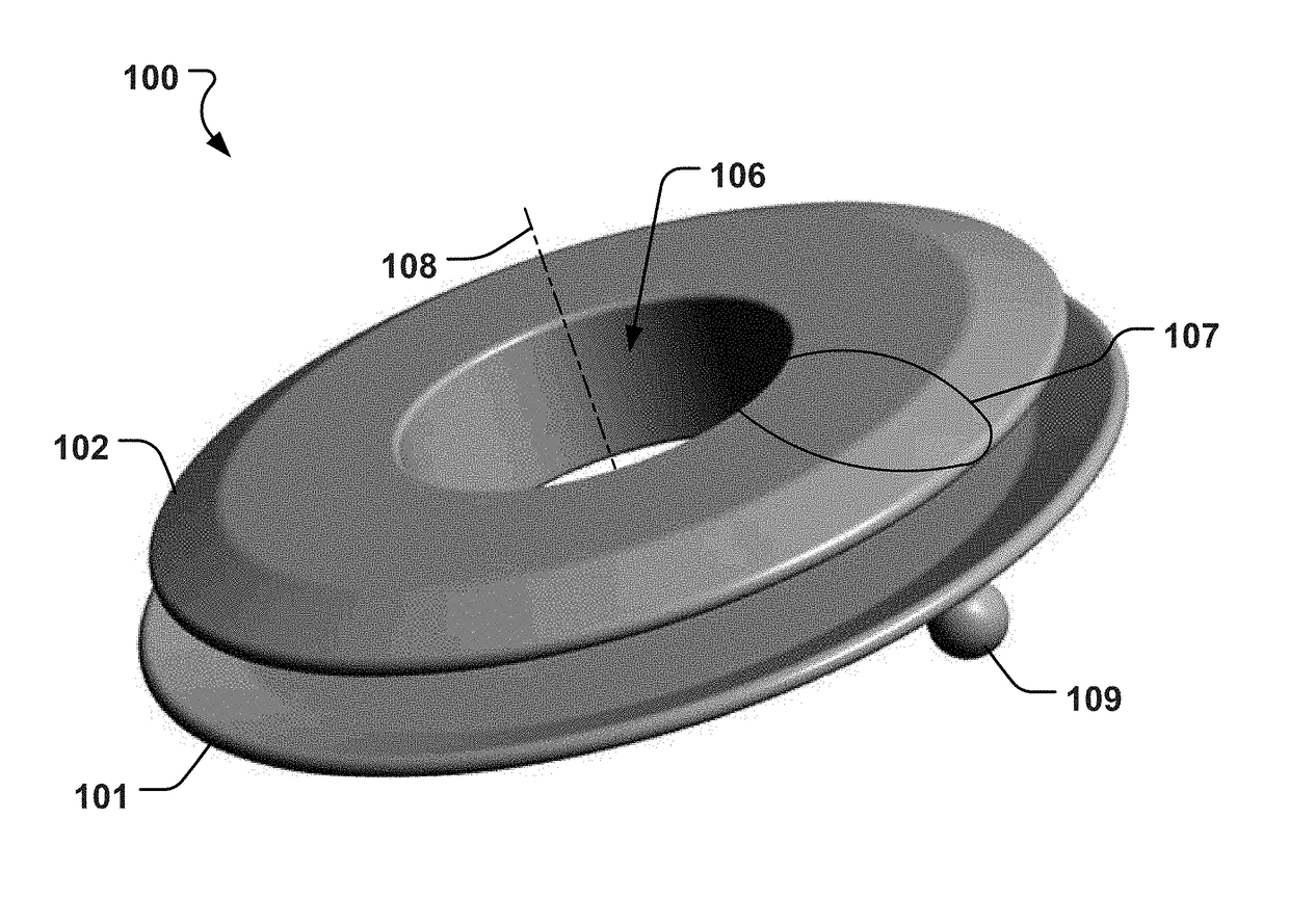
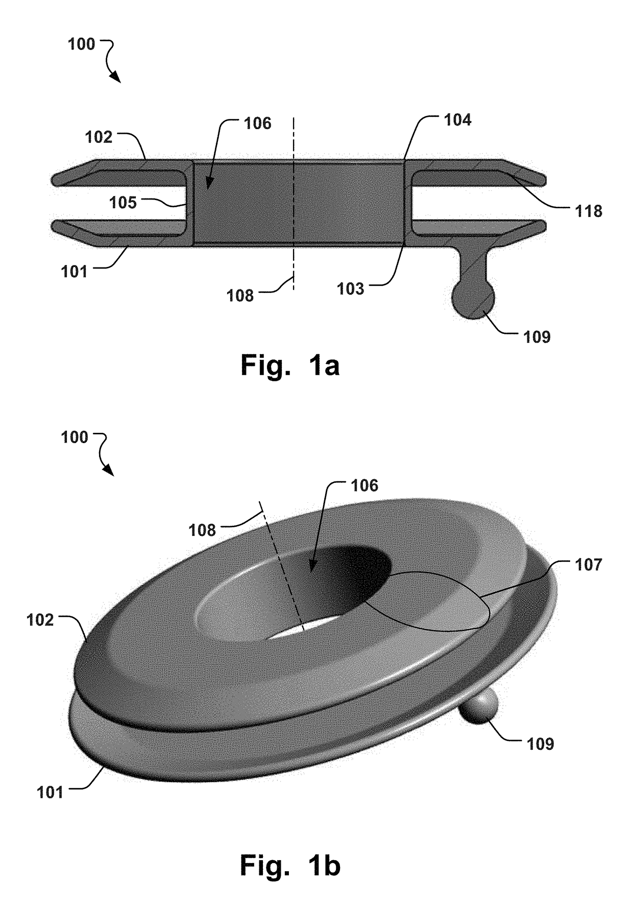
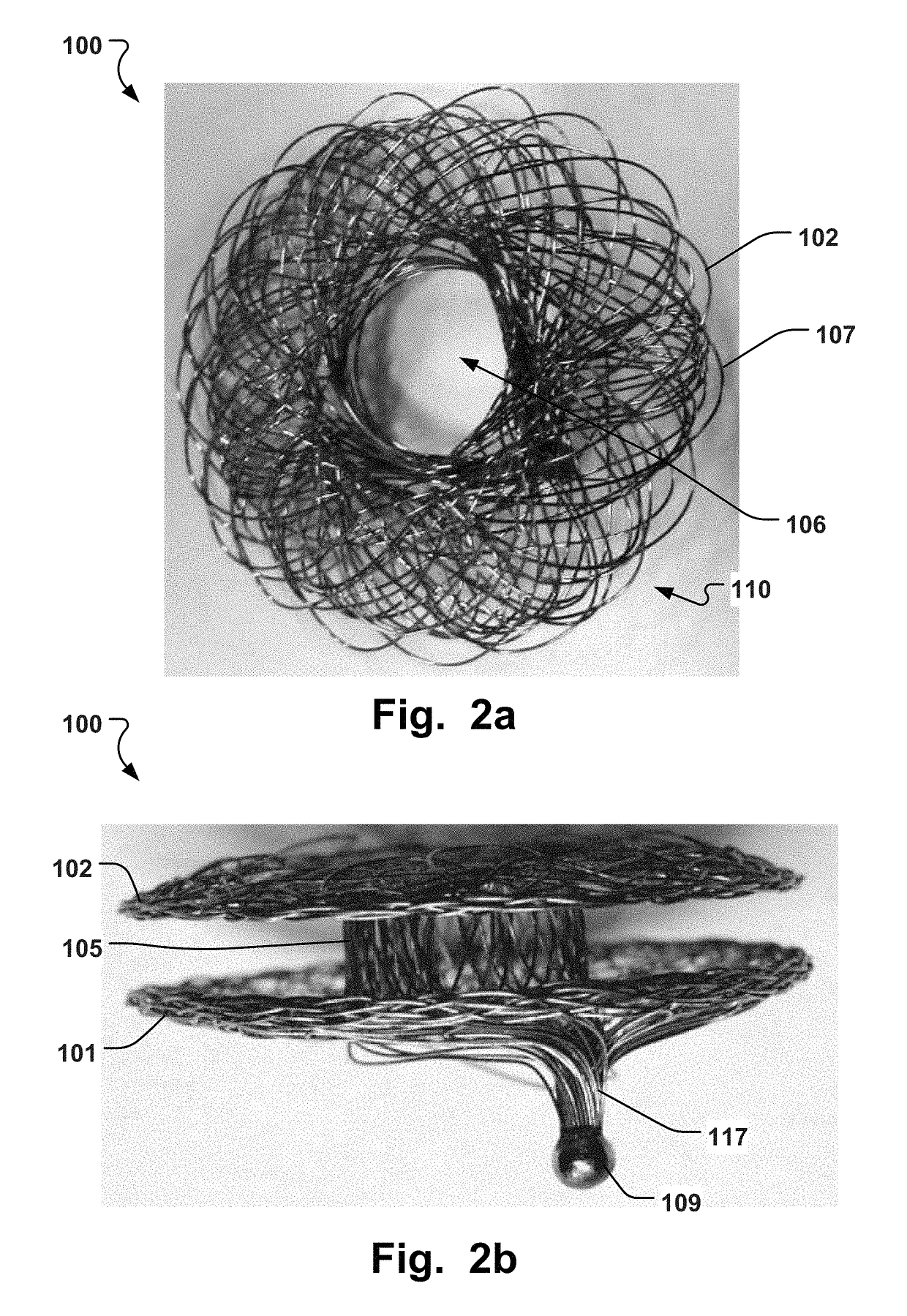
A blood flow regulator for creating a shunt in the heart, comprising; a proximal element having a general disc-shape, defined by a braid of one or more wires extending about a central aperture of the proximal element; a distal element having a general disc-shape, defined by a braid of one or more wires extending about a central aperture of the distal element; and a third element defining a neck section intermediate the proximal and distal elements and forming a cavity having a diameter no greater than a diameter of each of the distal and proximal elements, wherein said distal element comprises at least one loop of a wire extending radially outwardly from a center of the distal element and returning towards said center of said distal element.

Description

FIELD OF THE INVENTION[0001]This disclosure pertains in general to the field of medical implants. More particularly, the disclosure relates to a device suitable for implantation in the atrial septum in the heart of a mammal. The device providing a precise dimension for an opening in the septum, with a predetermined diameter, where the device remains open for a predetermined period of time, and serving to control flow rate across the septum.BACKGROUND OF THE INVENTION[0002]In a healthy heart which is composed of four chambers, atria collect the blood from body and the lungs, and the ventricles pump the blood to the lungs and the body. The oxygenated blood which is pumped by the left ventricles carries oxygen to the body. Deoxygenated blood is returned to the right heart via veins and pumped to the lungs via pulmonary artery originated from the right heart. The oxygenated blood in the lungs flows into the left atrium via pulmonary veins and then to the left ventricle where it is pumpe...

Claims


Application Information

Patent Timeline
Patent Type & Authority Applications(United States)
IPC IPC(8): A61F2/24A61F2/00A61M27/00
CPCA61F2/2493A61M27/002A61F2/0077A61F2240/001A61F2210/0004A61F2250/0048A61F2210/0076A61F2230/0008A61F2230/0071A61F2230/0095A61F2002/0086A61F2210/0014A61B17/0057A61B2017/00247A61B2017/00575A61B2017/00592A61B2017/00597A61B2017/00606A61B2017/00623
Inventor VETTUKATTIL, JOSEPH JOHNAKPINAR, MEHMET HAKAN
Owner OCCLUTECH GMBH
Learn More