
Antimicrobial coating for long-term disinfection of surfaces

Inactive Publication Date: 2017-09-28
THE HONG KONG UNIV OF SCI & TECH
View PDF12 Cites 29 Cited by
  • Summary
  • Abstract
  • Description
  • Claims
  • Application Information

AI Technical Summary

Benefits of technology

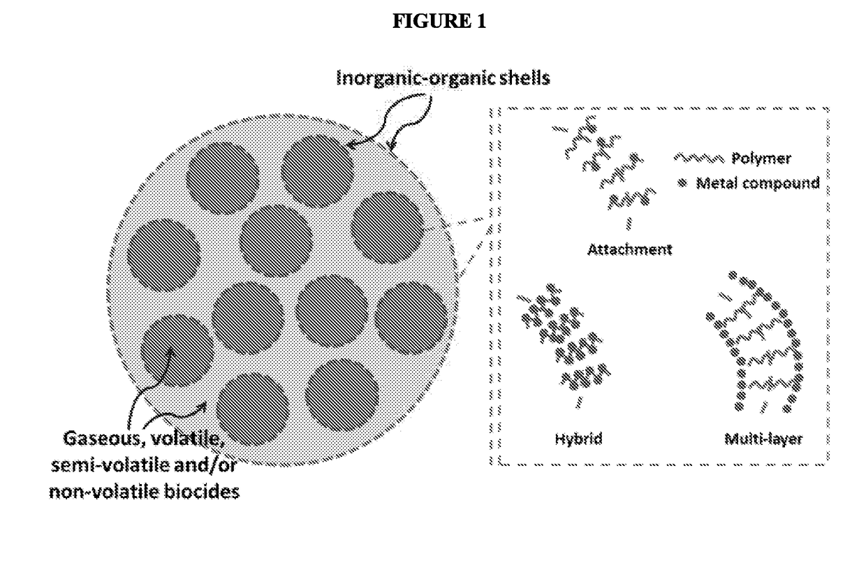
The present patent is related to an antimicrobial material that can be applied to porous materials or media. The material is made up of a biocide mixture (a biocidal component) and inorganic-organic shells (a permeable to the biocide's container). The inorganic materials can be metal oxides, metal complexes, metal salts, metal particles, or a combination of these. The inorganic materials are present in the inorganic-organic shells in a concentration of 0.5-95 wt%. The inorganic-organic shells enclose and contain the biocides, allowing for storage and release. The antimicrobial coating can be applied to porous materials or media using a method involving preparing a biocide mixture, preparing a suspension / solution of nonionic polymers and inorganic materials, preparing a stable emulsion of the biocide mixture encapsulated within inorganic-organic shells, and applying the antimicrobial coating on the porous material or medium. The antimicrobial coating provides a way to protect porous materials or media from microbial contamination.

Problems solved by technology

However a known problem with conventional filtration technology is the fact microbes trapped in filters remain viable to the extent they can grow in and colonize the filter.
For example, in an air filter the warm and humid environment encourages microbial growth and presents a two-fold problem.
Not only is filter performance degraded, but the colonization also poses a clear risk of contamination of the air to be filtered by the very pathogenic bacteria, viruses and fungi that the filter is designed to eliminate.
A further known problem of conventional filtration technology is the ability of ultra-small cells and viruses to penetrate the filter.
For example, photocatalytic disinfection requires an additional light source, is slow, sensitive to humidity and vulnerable to surface contamination.
The use of silver nanoparticles increases the material and manufacturing costs.
Though irradiation treatments are relatively safe and disinfect rapidly, the additional electrical devices and electricity result in higher device and disinfection costs.

Method used


Image

  • Antimicrobial coating for long-term disinfection of surfaces
  • Antimicrobial coating for long-term disinfection of surfaces
  • Antimicrobial coating for long-term disinfection of surfaces

Examples


example 1

[0066]Sodium chlorite powder was dissolved in 50 ml of distilled deionized water to prepare sodium chlorite solution with concentration of 0.1 wt % to 40 wt %. The sodium chlorite solution was then mixed with 0.1 g to 2 g of 30 wt % hydrogen peroxide.

example 2

[0067]Sodium chlorite powder was dissolved in 50 ml of distilled deionized water to prepare sodium chlorite solution with concentration of 0.1 wt % to 40 wt %. The sodium chlorite solution was then mixed with 0.01 ml to 10 ml of 3% to 8% sodium hypochlorite or potassium hypochlorite solution.

example 3

[0068]Sodium chlorite powder was dissolved in 50 ml of distilled deionized water to prepare sodium chlorite solution with concentration of 0.1 wt % to 40 wt %. The sodium chlorite solution was then mixed with solutions containing metal ions (Cu2+, Zn2+, Ag+). The final concentration of metal ions ranges from 30 ppm to 3000 ppm.


PUM

PropertyMeasurementUnit
Temperatureaaaaaaaaaa
Solubility (mass)aaaaaaaaaa
Antimicrobial propertiesaaaaaaaaaa

Abstract

Provided is an antimicrobial coating material comprising one or more biocides encapsulated in inorganic-organic shells. The antimicrobial coating material can be applied on porous materials or porous media to form and antimicrobial coating without changing the physical properties and the functions of porous materials or porous media. The coating provides a durable, multi-level antimicrobial performance at high temperature through contact-killing, release-killing, anti-adhesion and self-cleaning. Also provided is a method of producing the antimicrobial coating material.

Description

RELATED APPLICATIONS[0001]The present patent application claims priority to provisional U.S. Patent Application No. 62 / 071,276 filed Sep. 19, 2014, which was filed by the inventor hereof and is incorporated by reference herein in its entirety.BACKGROUND[0002]The present subject matter relates to materials possessing a combination of release-killing, contact-killing and anti-adhesion antimicrobial properties and details of their preparation, as well as physicochemical properties and methods of use for long-term disinfections of solid and porous surfaces.[0003]According to a World Health Organization report (www.who.int / mediacentre / factsheets / fs310 / en / ), airborne and waterborne pathogens, such as tuberculosis, lower respiratory infections and pulmonary infections are among the top ten causes of deaths accounting for millions of death each year. Currently, filtration technology remains the most effective and economical means for air and water purification and disinfection. However a kn...

Claims


Application Information

Patent Timeline
IPC IPC(8): C09D5/14A01N59/00A01N59/08A01N59/16A01N59/20B01D46/00A01N65/22A01N65/28A01N31/08A01N31/06B01J13/02B01J13/22A01N25/28A01N37/16
CPCC09D5/14A01N25/28A01N59/00A01N59/08A01N59/16A01N59/20B01D46/0028A01N65/22A01N65/28A01N31/08A01N31/06B01J13/02B01J13/22A01N37/16C08L91/00A01N65/00B01J13/08C09D7/63Y02A50/30A01N31/00A01N65/08A01N65/24A01N65/44
Inventor YEUNG, KING LUNLAI, YUE TAKHAN, WEILI, YINGLI, YAN
Owner THE HONG KONG UNIV OF SCI & TECH
Learn More