Wireless inductive power transfer

a technology of inductive power transfer and wireless, which is applied in the direction of transmission, electrical equipment, circuit arrangements, etc., can solve the problems of inconvenient use, inability to meet the needs of users, so as to improve communication, improve the support of a plurality, and improve the performance and/or operation of a wireless power transfer system.

Active Publication Date: 2017-09-28
KONINKLJIJKE PHILIPS NV
View PDF0 Cites 15 Cited by
  • Summary
  • Abstract
  • Description
  • Claims
  • Application Information

AI Technical Summary

Benefits of technology

[0038]The invention may provide improved performance and/or operation of a wireless power transfer system. In particular, improved support for a plurality of power receivers may be provided.
[0039]The approach may improve communication between power receivers and a power transmitter, and may in particular in many scenarios reduce the risk of communication errors, such as specifically the loss of data messages transmitted from power receivers by load modulation. The approach may specifically reduce the risk of conflicts or collisions between multiple power receivers load modulating the wireless inductive power signal. A flexible yet reliable sharing of a communication channel formed by load modulation of the wireless inductive power signal can be achieved.
[0040]The approach may allow differentiated communication where different communication ch

Problems solved by technology

However, this tends to be impractical and requires the user to physically insert connectors or otherwise establish a physical electrical contact.
It also tends to be inconvenient to the user by introducing lengths of wire.
Although, the use of internal batteries may avoid the need for a wired connection to a power supply during use, this only provides a partial solution as the batteries will need recharging (or replacing which is expensive).
The use of batteries may also add substantially to the weight and potentially cost and size of the devices.
Accordingly, the communication from the power transmitter to the power receiver is likely to be substantially restricted compared to the communication from the power receiver to the power transmitter.
However, a critical issue for such scenarios is that of how to enable suitable communication between one power transmitter and multiple power receivers without this resulting in conflicts and interference.
For example, if two power receivers individually use load modulation to transmit data messages to the power transmitter, the simultaneous communication of data messages from more than one power receiver will result in collisions an

Method used


Image

  • Wireless inductive power transfer
  • Wireless inductive power transfer
  • Wireless inductive power transfer

Examples


Embodiment Construction

[0074]The following description focuses on embodiments of the invention applicable to a wireless power transfer system utilizing a power transfer approach such as known from the Qi specification. However, it will be appreciated that the invention is not limited to this application but may be applied to many other wireless power transfer systems.

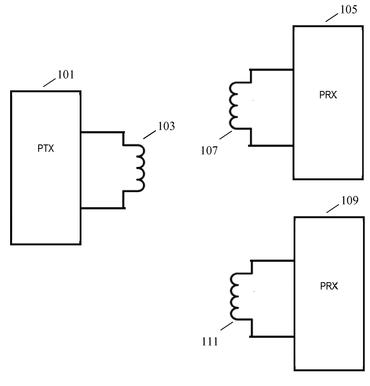
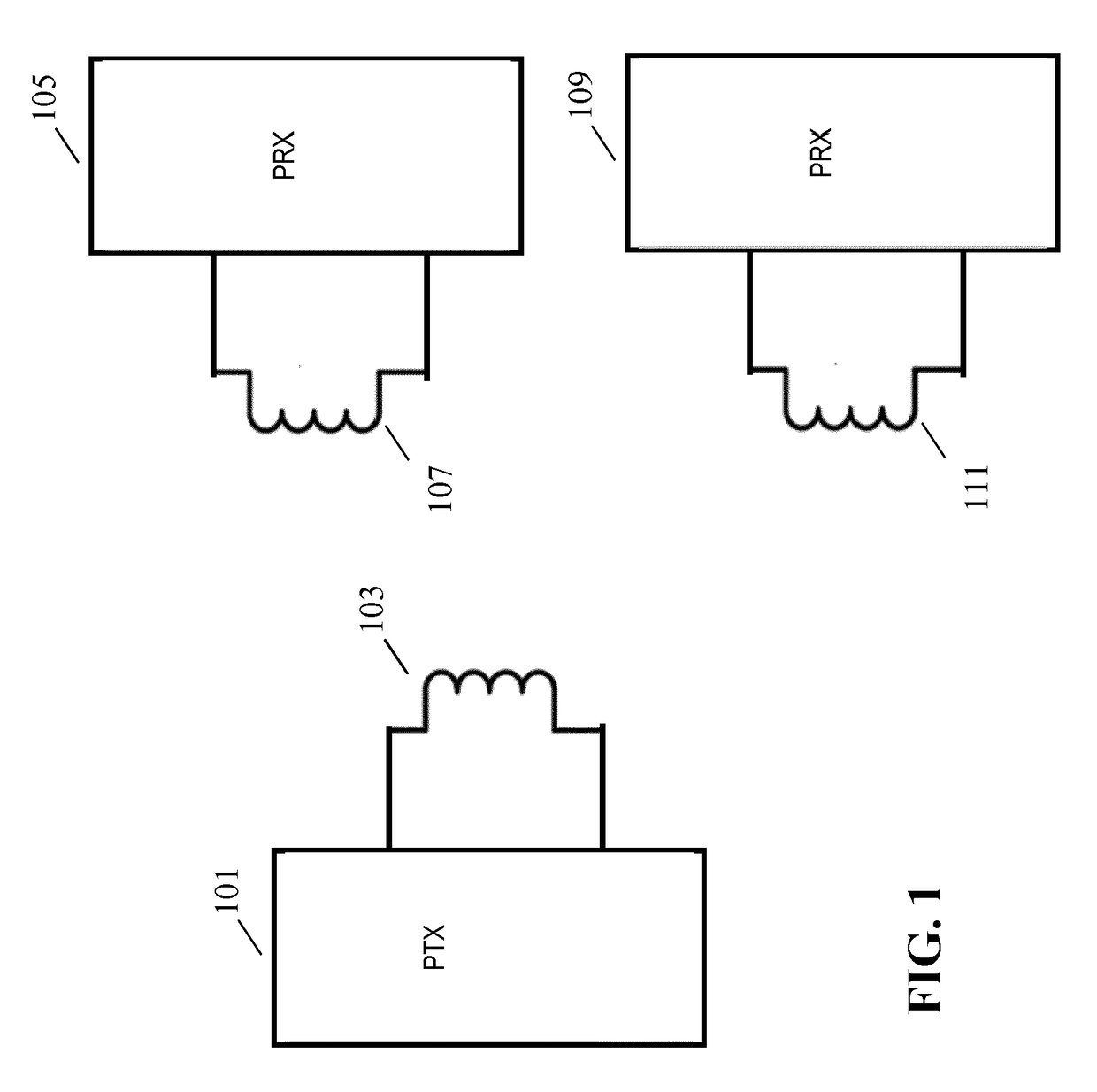
[0075]FIG. 1 illustrates an example of a power transfer system in accordance with some embodiments of the invention. The power transfer system comprises a power transmitter 101 which includes (or is coupled to) a transmitter coil / inductor 103. The system further comprises a first power receiver 105 which includes (or is coupled to) a receiver coil / inductor 107. The power transfer system also comprises a second power receiver 109 which includes (or is coupled to) a second receiver coil / inductor 111.

[0076]The system provides a wireless inductive power transfer from the power transmitter 101 to the first and second power receivers 105. Specifica...


PUM


Abstract

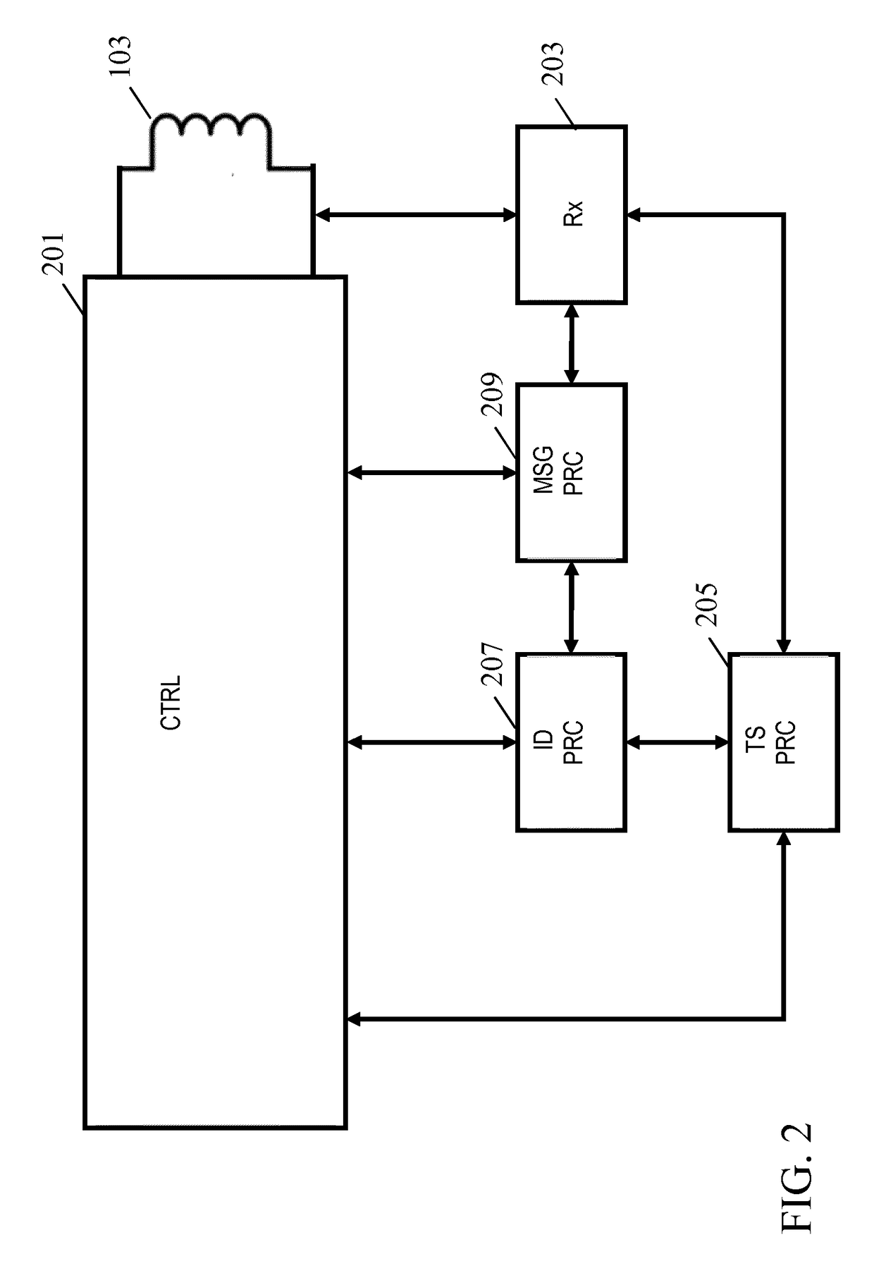
A wireless power transfer system comprises a power transmitter generating a wireless power signal providing power to a plurality of power receivers (105, 109). The power transmitter (101) comprises a receiver (203) receiving data messages from the power receivers (105, 109) on a load modulation channel divided into time slots. A time slot processor (205) allocates time slots as dedicated time slots for individual power receivers or as common time slots for load modulation by any power receiver (105, 109). An identity controller (207) links a temporary identity to each of the power receivers (105) and a message processor (209) determines the source power receiver for messages in response to temporary identity information in the messages. Specifically, the message processor (209) determines the source for a first message received in a common time slot as the first power receiver (105) if the temporary identity information in the first message is indicative of a temporary identity assigned to the first power receiver (105).

Description

FIELD OF THE INVENTION[0001]The invention relates to inductive power transfer and in particular, but not exclusively, to an inductive power transfer system compatible with some messages from a Qi power transfer system.BACKGROUND OF THE INVENTION[0002]The number and variety of portable and mobile devices in use have exploded in the last decade. For example, the use of mobile phones, tablets, media players etc. has become ubiquitous. Such devices are generally powered by internal batteries and the typical use scenario often requires recharging of batteries or direct wired powering of the device from an external power supply.[0003]Most present day systems require a wiring and / or explicit electrical contacts to be powered from an external power supply. However, this tends to be impractical and requires the user to physically insert connectors or otherwise establish a physical electrical contact. It also tends to be inconvenient to the user by introducing lengths of wire. Typically, powe...

Claims


Application Information

Patent Timeline
IPC IPC(8): H02J50/10H04B5/00H02J50/40
CPCH02J50/10H04B5/0037H02J50/40H02J5/005H02J50/80H02J50/12
Inventor STARING, ANTONIUS ADRIAAN MARIAVAN WAGENINGEN, ANDRIES
Owner KONINKLJIJKE PHILIPS NV
Why Eureka
Try Eureka