Gas-dissolved water production device and production method

Inactive Publication Date: 2017-10-05
EBARA CORP
View PDF2 Cites 5 Cited by
  • Summary
  • Abstract
  • Description
  • Claims
  • Application Information

AI Technical Summary

Benefits of technology

[0009]The present invention has been made in view of the above problems. An object of the present invention is to provide a gas-dissolved water production device capable of producing on...

Problems solved by technology

However, since the conventional ozone water supply device is a circulation type in which ozone water (unused ozone water) to be reused is circulated, the device ...

Method used


Image

  • Gas-dissolved water production device and production method
  • Gas-dissolved water production device and production method
  • Gas-dissolved water production device and production method

Examples


first embodiment

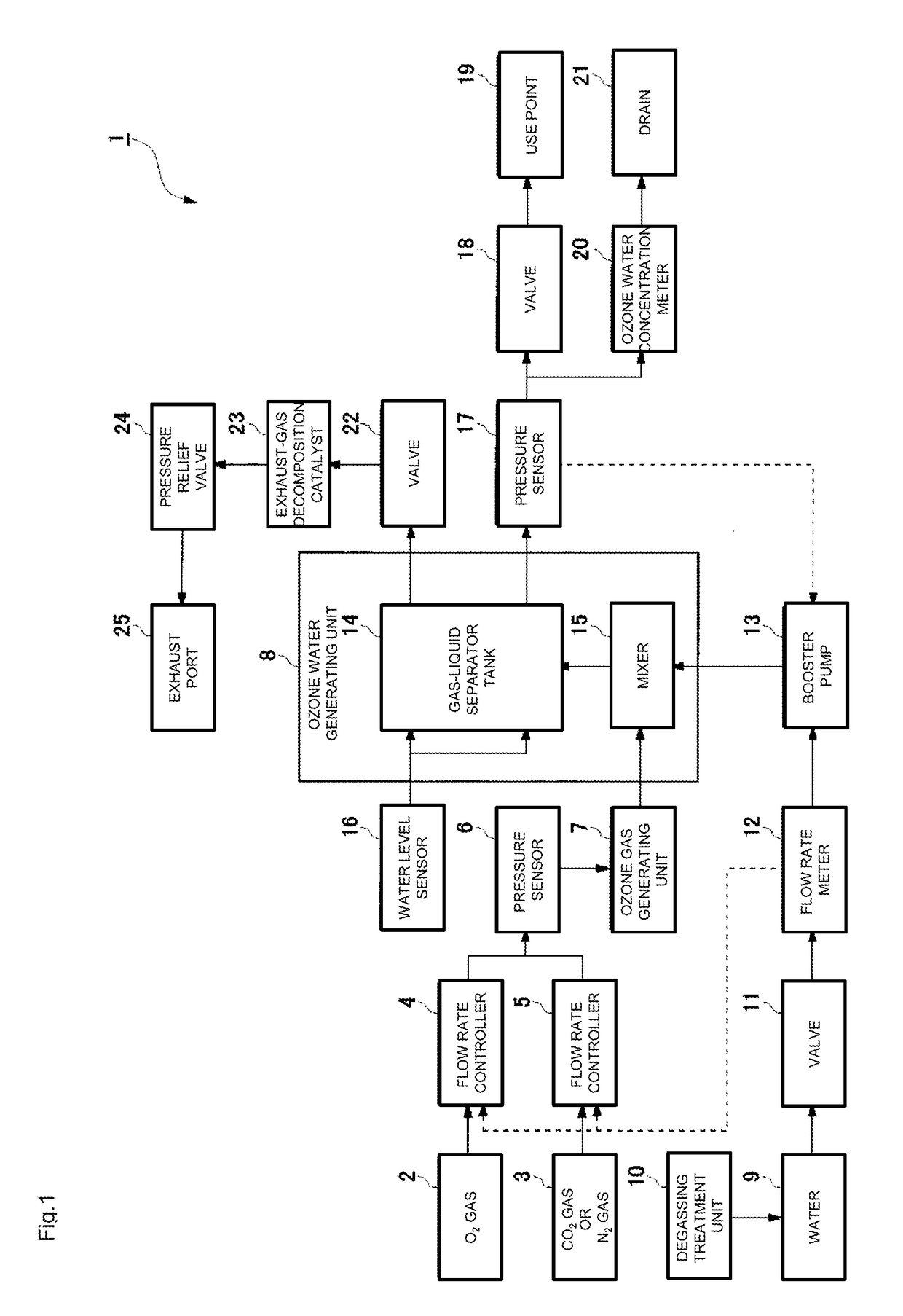
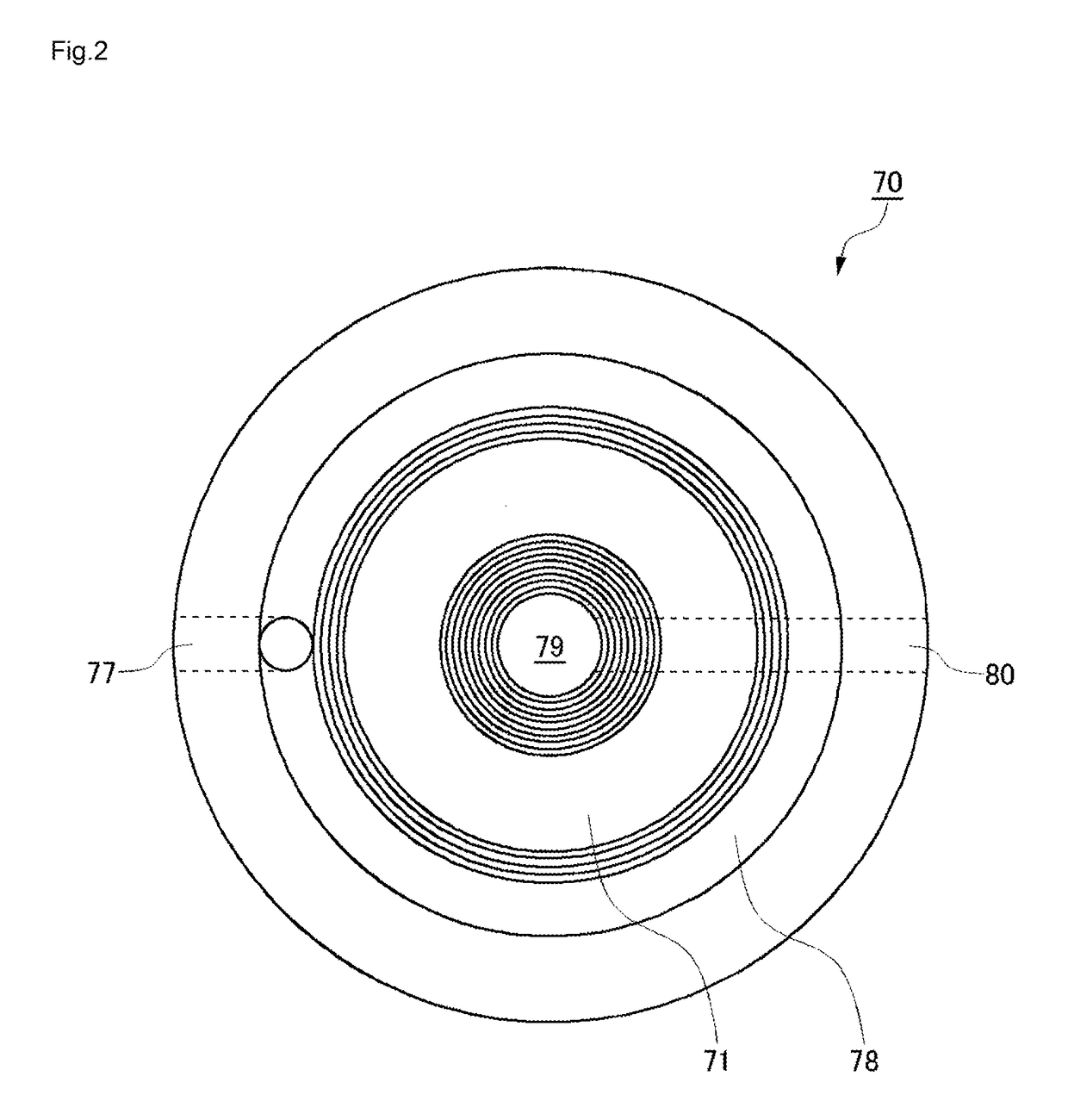
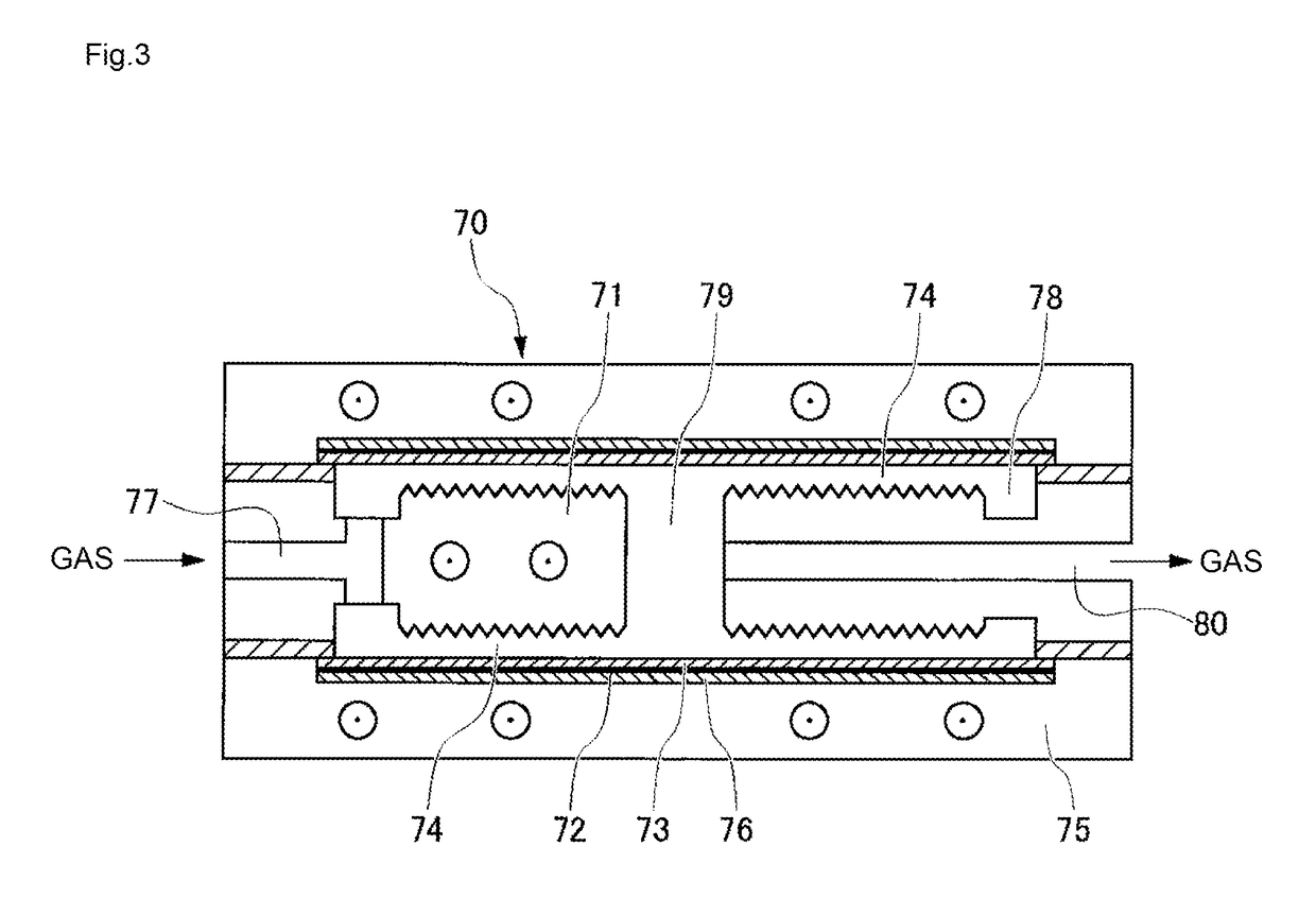
[0038]The configuration of a gas-dissolved water production device according to a first embodiment of the present invention will be described with reference to the drawings. FIG. 1 is a diagram illustrating the configuration of an ozone water production device according to the first embodiment. As illustrated in FIG. 1, the ozone water production device 1 includes respective supply sources 2, 3 of a first gas (O2 gas) and a second gas (CO2 gas or N2 gas), which are raw materials, and flow rate controllers 4, 5 that controls the flow rates of corresponding gases (the first gas and the second gas). The second gas (CO2 gas or N2 gas) is not necessarily required, and only the first gas (O2 gas) may be used. After the pressures of the first gas and the second gas are measured by a pressure sensor 6, the first gas and the second gas are sent to an ozone gas generating unit 7. The ozone gas generating unit 7 includes an electric discharge body 70 that generates ozone gas, through electric ...

second embodiment

[0059]Next, an ozone water production device according to a second embodiment of the present invention will be described. Here, features of the ozone water production device of the second embodiment different from those of the first embodiment will be mainly described. Unless otherwise specifically mentioned, the configuration and operations in the present embodiment are identical to those in the first embodiment.

[0060]FIG. 5 is a diagram illustrating the configuration of the ozone water production device according to the second embodiment. As illustrated in FIG. 5, the ozone water production device 1 of the present embodiment includes a control unit 26 configured to control the flow rates of the first gas (02 gas) and the second gas (CO2 gas and N2 gas), which are raw materials of ozone water.

[0061]The control unit 26 controls the flow rates of the first gas (O2 gas) and the second gas (CO2 gas or N2 gas), which are raw materials of ozone water, on the basis of a difference between...


PUM

PropertyMeasurementUnit
Thicknessaaaaaaaaaa
Pressureaaaaaaaaaa
Pressureaaaaaaaaaa

Abstract

An ozone water production device (1) includes: flow rate controllers (4, 5) that each control a flow rate of gas which is a raw material; a flow rate meter (12) that measures a flow rate of water which is a raw material; a booster pump (13) that controls pressure of the water; an ozone water generating unit (8) that generates ozone water by mixing ozone gas and the water; and a pressure sensor (17) that measures pressure of the ozone water which is to be supplied to a use point (19). The booster pump (13) controls the pressure of the water such that the pressure of the ozone water measured by the pressure sensor (17) is constant. The flow rate controllers (4, 5) each control the flow rate of the gas in accordance with the flow rate of the water measured by the flow rate meter (12).

Description

TECHNICAL FIELD[0001]The present invention relates to a gas-dissolved water production device that produces gas-dissolved water by mixing gas and water which are raw materials.BACKGROUND ART[0002]Recently, in a semiconductor device plant or a manufacturing plant for electronic components such as liquid crystal components, advancement of cleaning products has been facilitated due to increasingly complicated production processes and microfabricated circuit patterns. For example, a special liquid (called “cleaning liquid”) produced by dissolving a high-purity gas, or a high-purity gas and chemicals dissolved in functional water (e.g., ultrapure water) is used to remove fine particles, metals, organic matter, and the like attached on silicon wafers.[0003]As a cleaning processing method therefor, a “batch processing method” of repeatedly performing immersing and cleaning operations on a plurality of silicon wafers at the same time or a “sheet processing method” of performing chemical cle...

Claims


Application Information

Patent Timeline
IPC IPC(8): B01F3/04C01B13/11C02F1/78B01F15/00B01F5/04
CPCB01F15/00149B01F15/00422B01F15/00162B01F15/0022B01F5/0413C02F1/78C01B13/11B01F2003/04886C02F2103/04C02F2201/782C02F2209/03C02F2209/38C02F2209/40B01F2215/004H01L21/02052B01F3/0446B01F15/00357H01L21/67017C01B2201/64B01F23/232B01F23/237613B01F25/312B01F21/30B01F21/02B01F23/20B01F35/211B01F35/71B01F35/80B01F35/2113B01F35/2132B01F35/2213B01F35/2217B01F35/21112B01F2101/24B01F23/2326
Inventor OZAWA, SUGURUHARADA, MINORUTAKAHASHI, MUNEHITO
Owner EBARA CORP
Why Eureka
Try Eureka