
Three-dimensional modeling apparatus, three-dimensional model body manufacturing method, and three-dimensional modeling data

a three-dimensional model body and manufacturing method technology, applied in the field of three-dimensional modeling apparatus, can solve the problems of affecting the processing quality of model bodies, affecting the modeling operation itself, and occupying the inside of the chamber with a large amount of fumes, and achieve the effect of preventing the diffusion of fumes

Active Publication Date: 2017-10-05
CANON KK
View PDF3 Cites 37 Cited by
  • Summary
  • Abstract
  • Description
  • Claims
  • Application Information

AI Technical Summary

Benefits of technology

The present invention aims to prevent fume diffusion in a three-dimensional modeling apparatus during irradiation with an energy beam. The invention includes a cover that surrounds the modeling material and suppresses fume diffusion, and a stream regulating mechanism that removes fumes from the modeling area. The cover can also be moved to allow the energy beam to pass through. The technical effect of this invention is the efficient prevention of fume diffusion, improving the accuracy and quality of the three-dimensional modeling process.

Problems solved by technology

A problem has been known; that is, if this emission is left, repetitive layer formation finally fills the inside of the chamber with a large amount of fumes, which adhere onto the laser transmitting window and dwell on the laser optical path.
The phenomena have a possibility of affecting the model body processing quality, for example, modeling accuracy.
In an extreme case, there is a possibility that the modeling operation itself becomes impossible.
Unfortunately, according to the configuration of Japanese Patent Application Laid-Open No. 2010-265530, the timing of gas supply and gas collection and flow rate balance can cause the inside of the cover frame to have a positive pressure.
Consequently, there are problems in that fumes flow out of the cover frame beyond the bottom of this frame, and fumes dwell on the laser optical path.
Furthermore, there is a possibility that fumes that have not been collected by the gas collector and dwell adhere onto the window on the top surface of the cover frame that allows a laser beam to pass.

Method used


Image

  • Three-dimensional modeling apparatus, three-dimensional model body manufacturing method, and three-dimensional modeling data
  • Three-dimensional modeling apparatus, three-dimensional model body manufacturing method, and three-dimensional modeling data
  • Three-dimensional modeling apparatus, three-dimensional model body manufacturing method, and three-dimensional modeling data

Examples


embodiment 1

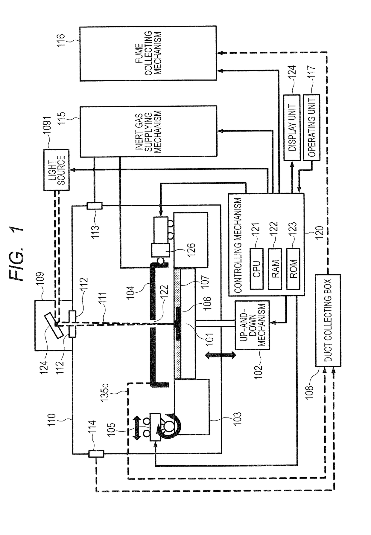
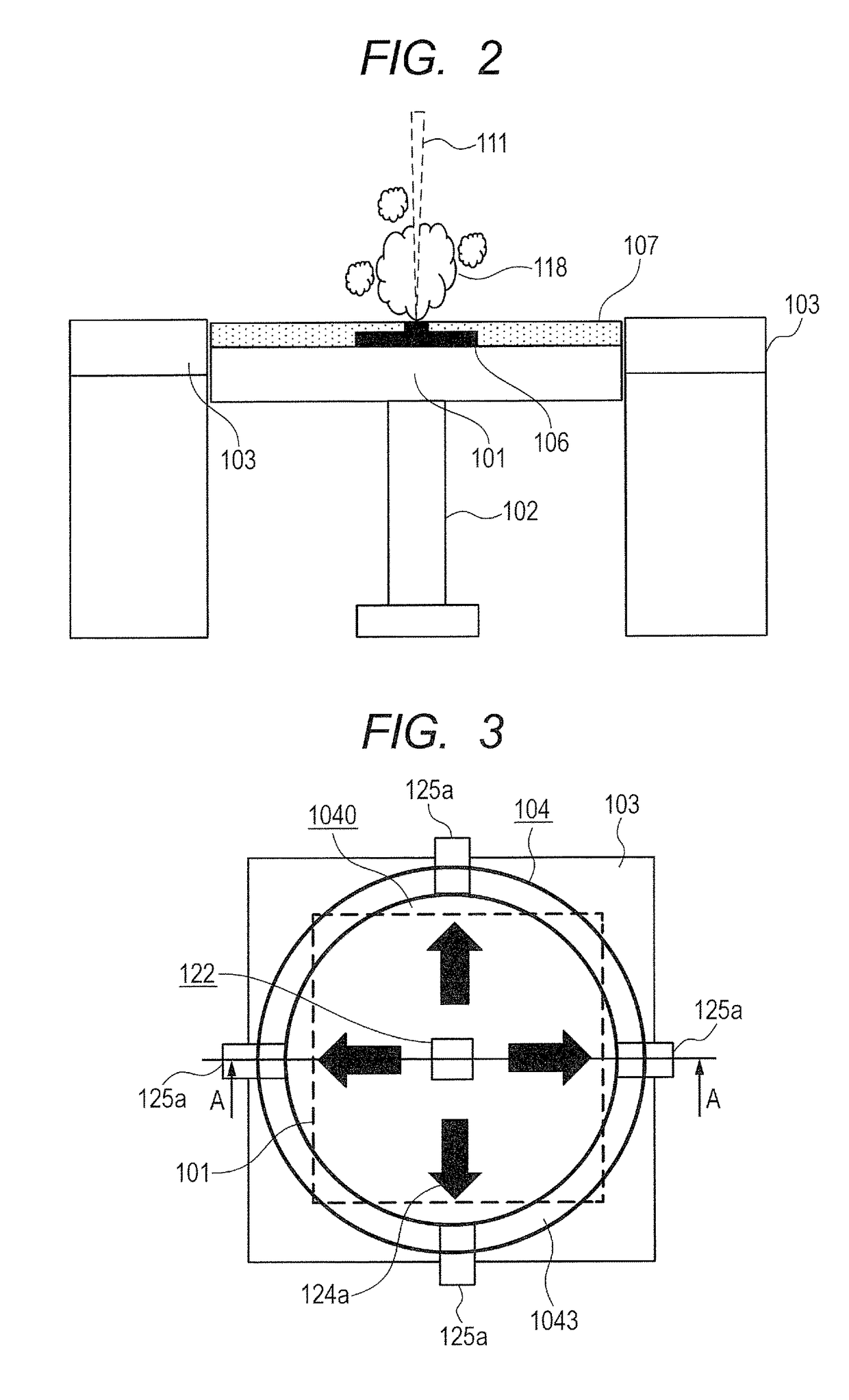
[0030]One configuration example of a three-dimensional modeling apparatus that uses a powder bed fused bonding method and can implement the present invention is described with reference to FIGS. 1 and 2. FIG. 1 illustrates a basic configuration of the three-dimensional modeling apparatus that can implement the present invention. FIG. 1 illustrates a schematic configuration that is common not only to this embodiment but also to the other embodiments described later. FIG. 2 illustrates an enlarged view around a modeling stage of the three-dimensional modeling apparatus of FIG. 1 and, in particular, illustrates an image of fumes emitted by fusing material powder during modeling.

[0031]As illustrated in FIG. 1, this apparatus includes a modeling stage 101 for allowing a three-dimensionally shaped model body to be modeled on this stage. The modeling stage 101 can be moved up and down by a modeling table 103 so as to be gradually moved down, for example, according to the advancement of lay...

embodiment 2

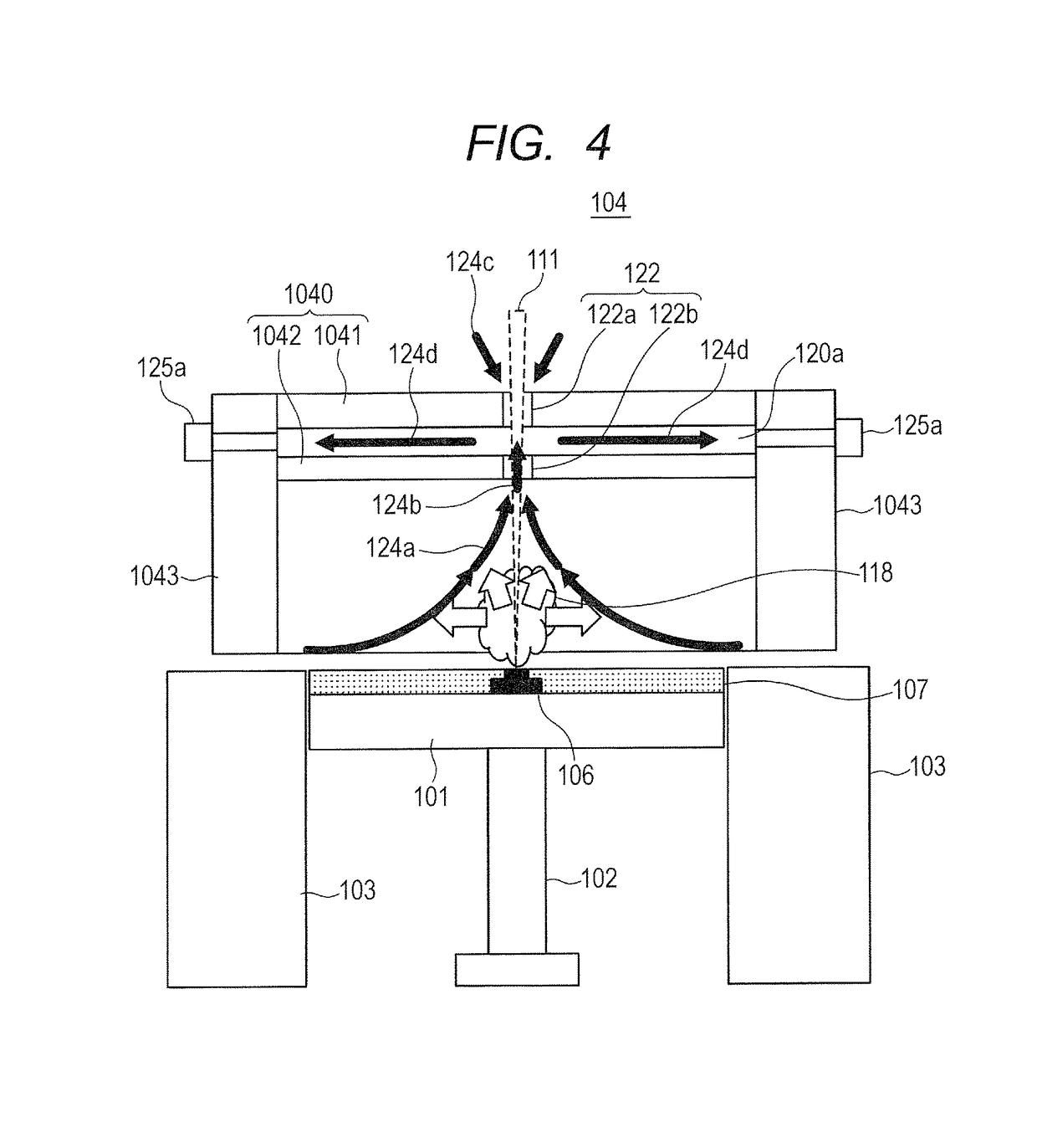
[0067]The above Embodiment 1 describes one example of the cover 104 that includes the outer partition 1041 and the inner partition 1042, and further includes the upper structure 1040 that forms the gas stream path 120a. The above Embodiment 1 describes the example that regulates the atmosphere containing the fumes (118) by controlling the pressure in the gas stream path 120a of the cover 104 to be negative using the four fittings 125a, and prevents the atmosphere from leaking to the outside of the cover 104.

[0068]However, to achieve the same object, the configuration of the gas stream path (120c in this embodiment), and the mode of pressure control and stream regulating in the gas stream path (120c) can be changed as described below, for example.

[0069]FIGS. 5 and 6 illustrate the configuration and operation of the cover 104 of this Embodiment 2. The illustrated mode is the same as that of FIGS. 3 and 4. In FIGS. 5 and 6, the same or similar members are assigned the same reference si...

embodiment 3

[0081]FIGS. 7 and 8 illustrate the configuration of a cover 104 in this embodiment in a manner equivalent to that in FIGS. 3 and 4 (FIGS. 5 and 6).

[0082]In Embodiments 1 and 2 described above, the gas stream path 120a or gas stream path 120c of the cover 104 communicates with the fitting 125a or the fitting 125c that serves as a gas communicating path for exhausting gas from the inside. The openings 122a and 122b (permeation holes) are formed in the outer partition 1041 and the inner partition 1042, respectively, that forms the gas stream path 120a and the gas stream path 120c, to allow the laser light 111 to be transmitted (pass).

[0083]Unlike these configurations, Embodiment 3 concerned, as illustrated in FIG. 8, the upper structure 119 of the cover 104 is not provided with any opening through the outer partition 119a and the inner partition 119b that form the gas stream path 120d.

[0084]In this Embodiment 3, the outer partition 119a that forms the gas stream path 120d is made of t...


PUM

PropertyMeasurementUnit
diametersaaaaaaaaaa
energyaaaaaaaaaa
pressureaaaaaaaaaa

Abstract

In a three-dimensional modeling apparatus, diffusion of fumes generated around the modeling stage accompanying irradiation with an energy beam can be efficiently prevented. Three-dimensional modeling is performed by repeating scanning a modeling material arranged on a modeling stage with laser light to form a solidified layer. A cover is provided that locally surrounds an irradiation portion on the modeling material arranged on the modeling stage irradiated with the laser light, and suppresses diffusion of the fumes caused by irradiation with the laser light. In the cover, a stream of gas containing the fumes is regulated so as to cause the fumes to flow toward an upward portion inside the cover apart from the irradiated portion irradiated with the laser light.

Description

BACKGROUND OF THE INVENTIONField of the Invention[0001]The present invention relates to a three-dimensional modeling apparatus that performs three-dimensional modeling by repeating a step of scanning a modeling material arranged on a modeling stage with an energy beam to form a solidified layer.Description of the Related Art[0002]A three-dimensional modeling apparatus that uses a powder bed fused bonding method, is one of three-dimensional layer-stacking modeling technique schemes, and is called a three-dimensional printer, has been implemented. This type of three-dimensional modeling apparatus performs three-dimensional modeling by repeating a step of selectively, radiationally heating material powder laid by a powder spreading roller with an energy beam to solidify the powder, thus stacking multiple layers. For example, a laser beam is used as the energy beam for heating and solidifying the material powder. In the following description, a case is mainly referred to where the energ...

Claims


Application Information

Patent Timeline
Patent Type & Authority Applications(United States)
IPC IPC(8): B22F3/105B33Y50/02B33Y30/00B29C67/00B33Y10/00
CPCB29C67/0077B29C67/0088B29C67/0085B33Y10/00B22F3/1055B33Y50/02B29K2105/251B22F2003/1057B22F2998/10B33Y30/00B33Y40/00B22F10/32B22F12/41B22F10/366B22F12/70B22F10/10B22F12/63B22F10/20B29C64/153B29C64/371Y02P10/25
Inventor YASUDA, SHINYAFUJIMOTO, KIMIHIROZHANG, DEXUSUZUKI, TAKAMUNETAKAI, TOSHIHIROTAKAHASHI, YUTAKAHARIGAE, TAKAHIRO
Owner CANON KK
Learn More