Power-Transmitting Friction Belt and Method for Manufacturing Same

Active Publication Date: 2017-10-05
MITSUBOSHI BELTING LTD
View PDF1 Cites 12 Cited by
  • Summary
  • Abstract
  • Description
  • Claims
  • Application Information

AI Technical Summary

Benefits of technology

[0026]In the present invention, since water absorptive fibers are contained in a fibrous member to cover a frictional power transmission surface and an inorganic powder is made to exist in at least the surface of the fibrous member, the friction coefficient in a dry state (DRY) on the frictional power transmission surface (power transmission surface) can be prevented from increasing and the friction coefficient in exposure to water (WET) thereof can be prevented from lowering, that is, the difference in the friction coefficient between in a dry state (DRY) and in exposure to water (WET) can be reduced. Therefore, quietness (silence, sound generation resistance) can

Problems solved by technology

Such a power transmission belt has a problem that it generates noise when exposed to water.
For example, in running in rain or the like case, when water penetrates into an engine room and the water further penetrates into the space between the frictional power transmission surface (power transmission surface) of the belt and pulleys, since the frictional power transmission surface is poorly wettable with water and tends to repel water, the water penetration condition could not be uniform between the frictional power transmission surface of the belt and the pulleys.
However, in the embodiment of Patent Document 1, a powder layer must be formed on the forming surface of a mold, and therefore the molding and vulcanizing step is complicated and the mold is easily stained.
Moreover, vulcanized rubber may readily bleed out on the surface of the fabric layer to cause stick-slip sound generation.
Furtherm

Method used


Image

  • Power-Transmitting Friction Belt and Method for Manufacturing Same
  • Power-Transmitting Friction Belt and Method for Manufacturing Same
  • Power-Transmitting Friction Belt and Method for Manufacturing Same

Examples


examples

[0102]The present invention is described in more detail hereinunder based on Examples thereof, but the present invention is not restricted by these Examples. A method of measuring the deposition amount of surfactant, and measurement methods and evaluation methods for physical properties are explained below.

[Rubber Composition]

[0103]A rubber composition shown in Table 1 was kneaded with a Banbury mixer, and the kneaded rubber was led to pass between calender rolls to produce an unvulcanized rolled rubber sheet having a predetermined thickness (sheet for compression layer). Furthermore, by using a rubber composition A shown in Table 1, a sheet for adhesive layer and a sheet for tension layer were produced in the same manner as above. The components in Table 1 are as follows.

[0104]EPDM: “NORDEL IP4640”, manufactured by Dow Chemical Company

[0105]Zinc oxide: “Zinc Oxide No. 3”, manufactured by Seido Chemical Industry Co., Ltd.

[0106]Carbon black: “SEAST V” having an average article diamet...

examples 1 to 3

[0112]A cotton spun yarn (No. 40, one yarn) as water absorbent fibers, and a PTT / PET conjugate composite yarn (fineness 84 dtex) as second fibers were knitted to produce a knitted fabric (fibrous member) having a weft knitting texture (moss stitch, 2 layers). In respective Examples, a knitted fabric having a different thickness and knitted fabric density was used as the fibrous member.

[Formation of Preliminary V-Ribbed Belt]

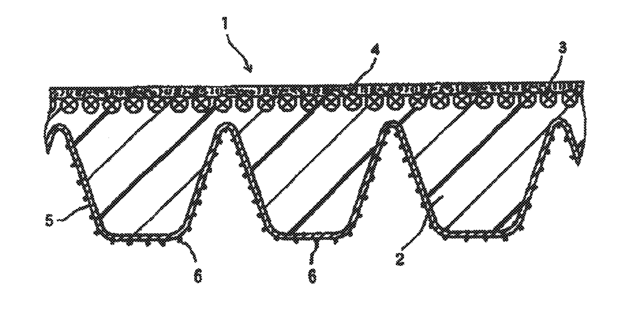
[0113]A cylindrical inner mold equipped with a flexible jacket around the outer peripheral surface thereof was used. An unvulcanized sheet for tension layer was wound on the flexible jacket on the outer peripheral surface, and a cord (twisted cord) to be a tension member was helically spun on the sheet, and further, thereof were wound an unvulcanized sheet for compression layer and a fibrous member (knitted fabric) to produce a laminate structure. As the cord, a polyester cord having a configuration of 1100 dtex / 2×3 was used. For enhancing the adhesiveness to rub...

examples 4 to 5

[0116]A V-ribbed belt was produced in the same manner as in Example 3, except that the amount of the inorganic powder to be sprayed onto the surface of the fibrous member was changed to 130 g / m2 or 150 g / m2.


PUM

PropertyMeasurementUnit
Fractionaaaaaaaaaa
Thicknessaaaaaaaaaa
Percent by massaaaaaaaaaa

Abstract

The present invention relates to a frictional power transmission belt (1) having a frictional power transmission surface in which the frictional power transmission surface is covered with a fibrous member (5) at least containing water absorptive fibers and an inorganic powder (6) exists in at least a surface of the fibrous member.

Description

TECHNICAL FIELD[0001]The present invention relates to a frictional power transmission belt (V-ribbed belt, etc.) of which the frictional power transmission surfaces are covered with a fabric (knitted fabric, etc.) and which has a high transmission efficiency and improved quietness (silence or sound generation resistance), and to a method for manufacturing it.BACKGROUND ART[0002]Accessories such as air compressors and alternators for automobiles are driven with a belt power-transmission system using an engine as the driving source. For the power transmission belt in the belt power-transmission system is utilized a V-ribbed belt, which contains a tension layer forming the back of the belt, a compression layer formed on one surface of the tension layer, having plural V-shaped ribs formed to extend in the perimeter direction of the belt and being a frictional power transmission surface against pulleys, and a tension member embedded between the tension layer and the compression layer to ...

Claims


Application Information

Patent Timeline
IPC IPC(8): F16G5/08B32B25/10F16G5/20B32B5/30F16G1/10B29D29/08B32B5/02
CPCF16G5/08B29D29/08B32B25/10B32B2433/04B32B5/30F16G1/10F16G5/20B32B5/026B29D29/10D03D1/0094
Inventor MITSUTOMI, MANABUKOJIMA, HIROYUKIKOJIMA, KAZUYOSUZUMEGANO, YUSUKE
Owner MITSUBOSHI BELTING LTD
Why Eureka
Try Eureka