Apparatus and method for controlling flow control valve for high pressure fuel pump

a flow control valve and high-pressure technology, applied in the direction of electric control, machines/engines, instruments, etc., can solve the problems of increasing dissatisfaction of drivers, noise discharged to the outer, and the solenoid operating the flow control valve generates vibration and noise, so as to reduce the operation speed of the plunger, reduce the noise and vibration due to collision between the plunger and the core

Active Publication Date: 2017-10-12
MOTONIC
View PDF3 Cites 16 Cited by
  • Summary
  • Abstract
  • Description
  • Claims
  • Application Information

AI Technical Summary

Benefits of technology

[0027]Therefore, according to the present invention, the noise and the vibration due to collision between the plunger and the core can be attenuated by reducing an operation speed of the plunger provided in the flow control valve.

Problems solved by technology

However, the solenoid for operating the flow control valve generates a vibration and a noise due to an impact when the coil provided in the solenoid collides with a stopper provided at the inlet-side check valve upon operation of the high-pressure fuel pump.
Particularly, the inlet-side check valve of the solenoid generates a high frequency noise during an operation at a lower speed section where the engine is relatively silent, thus the high-pressure fuel pump according to the related art causes an increase of dissatisfaction to a driver due to the noise.
In addition, the high-pressure fuel pump for the GDI type engine according to the related art has a problem in that a spring mount unit provided in the solenoid is formed in an open type and coupled to an outer side of a body of the high-pressure fuel pump, such that the noise upon operation is discharged to an outer side of the high-pressure fuel pump.
However, there is a limit to remove the vibration and the noise completely upon operation of an actuator even though the configuration of patent document 3 is applied.
In addition, the high-pressure fuel pump for the GDI type engine according to the related art has problems in that an amount of a current consumption increases and a failure or damage on components incurs due to heat generated from the coil as a current is continuously supplied to the coil of the solenoid when the flow control valve operates.

Method used


Image

  • Apparatus and method for controlling flow control valve for high pressure fuel pump
  • Apparatus and method for controlling flow control valve for high pressure fuel pump
  • Apparatus and method for controlling flow control valve for high pressure fuel pump

Examples


Embodiment Construction

[0035]An apparatus and a method for controlling a flow control valve for a high-pressure fuel pump according to a preferred embodiment of the present invention will be described in detail with reference to the accompanying drawings.

[0036]Hereinafter, for the convenience of explanation, a flow control valve provided in a high-pressure fuel pump for a GDI type engine will be used in the description.

[0037]However, the present invention is not limited thereto, and it may be applied not only to the GDI type engine but also to various internal combustion engines such as a direct injection type LPG engine capable of directly injecting various kinds of fuel into a combustion chamber by pressurizing the fuel at the high pressure.

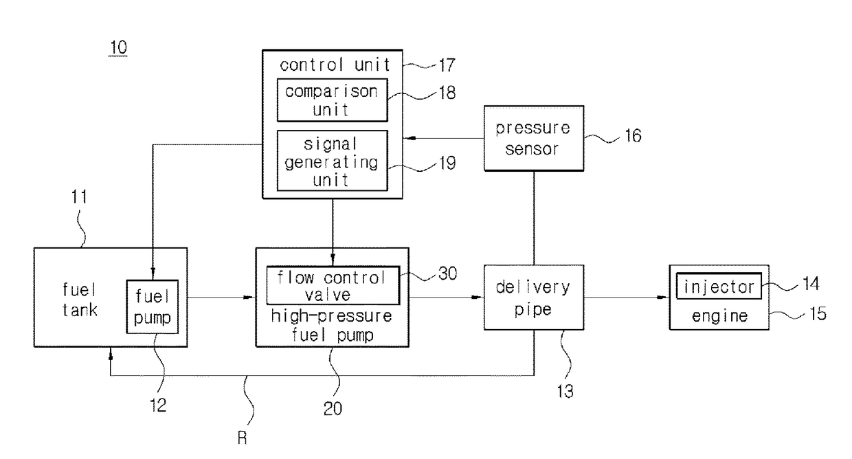
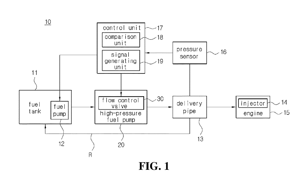
[0038]FIG. 1 is a block diagram showing a fuel supply system using an apparatus for controlling a flow control valve for a high-pressure fuel pump according to a preferred embodiment of the present invention.

[0039]As shown in FIG. 1 according to a preferable embodime...


PUM


Abstract

An apparatus and a method for controlling a flow control valve for a high-pressure fuel pump include: a pressure sensor for fuel in a delivery pipe; a control unit for controlling an operation of a flow control valve by controlling a current applied to a coil; a power switching unit for supplying or blocking driving power supplied to the flow control valve based on a control signal of the control unit; and a current adjustment unit electrically connected/disconnected with the flow control valve by the power switching unit to reduce a current supplied to the flow control valve when the current adjustment unit is connected with the flow control valve. Therefore, a noise and a vibration by collision between the plunger and the core upon closing the flow control valve may be attenuated by adjusting a current amount applied to the coil.

Description

BACKGROUND OF THE INVENTIONField of the Invention[0001]The present invention relates to an apparatus and a method for controlling a flow control valve for a high-pressure fuel pump, and more specifically, to an apparatus and a method for controlling a flow control valve for a high-pressure fuel pump, which compress fuel at high pressure after an engine inhales and compresses air so as to supply the fuel to an injector for directly injecting the fuel into a cylinder.Description of the Related Art[0002]To improve fuel efficiency and performance of a gasoline engine, a technology for a gasoline direct injection (GDI) type engine is under development.[0003]A usual gasoline engine generates motive power by a process of intake / compression / combustion / explosion / exhaust of an air / fuel mixture, whereas the GDI type engine inhales and compresses only air and then injects fuel, which is similar to a compression ignition system of a diesel engine.[0004]Accordingly, the GDI type engine can implem...

Claims


Application Information

Patent Timeline
Patent Type & Authority Applications(United States)
IPC IPC(8): F02D41/30F02M59/10F02M65/00F02M59/46
CPCF02D41/3005F02M59/466F02D2200/101F02M65/003F02M59/102F02D41/20F02D41/3845F02M59/366F02D2041/2003F02D2041/2027F02D2041/2037F02D2200/0602F02M55/02F02M59/025F02M59/10F02M59/26F02M59/46
Inventor LEE, SANG RYULJEON, WAN JAELEE, JUN HYEOKKIM, HYUNG SOOKIM, HAE JINCHOI, KYU SUNGPARK, YEONG DONG
Owner MOTONIC
Why Eureka
Try Eureka