Surface defects evaluation system and method for spherical optical components

a technology of optical components and defects, applied in the field of machine vision inspection, can solve the problems of secondary damage, subjectivity and uncertainty of visual inspection, energy loss, etc., and achieve the effect of avoiding the influence of subjectivity on the results and enhancing the efficiency and precision of inspection

Active Publication Date: 2017-10-12
ZHEJIANG UNIV
View PDF0 Cites 38 Cited by
  • Summary
  • Abstract
  • Description
  • Claims
  • Application Information

AI Technical Summary

Benefits of technology

[0007]Spherical surface defects evaluation system (SSDES) comprises a defect imaging subsystem and a control subsystem. The defect imaging subsystem is adapted to acquire microscopic scattering dark-field images suitable for digital image processing. The control subsystem is adapted to drive the movements of various parts of the defect imaging subsystem, to realize automatic scanning and inspection of defects on the spherical surface. The defect imaging subsystem comprises an illumination unit, a microscopic scattering dark-field imaging (MS-DFI) unit, a spatial position and posture adjustment (SPPA) unit and a centering unit. The illumination unit is adapted to provide dark-field illumination for microscopic scattering dark-field imaging of spherical surface. The MS-DFI unit is adapted to collect scatter light induced by the surface and image. The SPPA unit is adapted to achieve five-dimensional spatial position and attitude adjustment including three-dimensional translation, rotation and swing, easy to acquire sharp images at various locations on the surface of the spherical optical component. The centering unit is adapted to analyze the position of the curvature center of the component. The movement and the adjustment of the illumination unit, the MS-DFI unit, the SPPA unit and the centering unit are driven by the control subsystem.
[0056]① Projective sub-aperture images are denoised to remove the effect of background noise on stitching accuracy.
[0072]The present invention achieves the automatic quantitative evaluation for surface defects of spherical optical components, which not only liberates the inspectors from the heavy work of visual inspection, but also considerably enhance the efficiency and precision of the inspection, avoiding the influence of subjectivity on the results. Eventually, reliable numerical basis for the use and process of spherical optical components is provided.

Problems solved by technology

However, defects such as scratches and digs on the surface of components can not only affect the imaging quality of optical systems, but also generate unnecessary scattering and diffraction light resulting in energy loss in the high-power laser system, which may also lead to a secondary damage because of the high energy.
However, the visual inspection suffers from subjectivity and uncertainty.
It is greatly influenced by the proficiency of the inspector and can't provide quantitative description of defects information.
Furthermore, a long-time inspection can cause eyes fatigue resulting in lower reliability.

Method used


Image

  • Surface defects evaluation system and method for spherical optical components
  • Surface defects evaluation system and method for spherical optical components
  • Surface defects evaluation system and method for spherical optical components

Examples


first embodiment

[0116]Hereafter, a first embodiment of the present invention will be described in detail with reference to FIGS. 1 to 25, which describes surface defects evaluation system and method for convex spherical optical components.

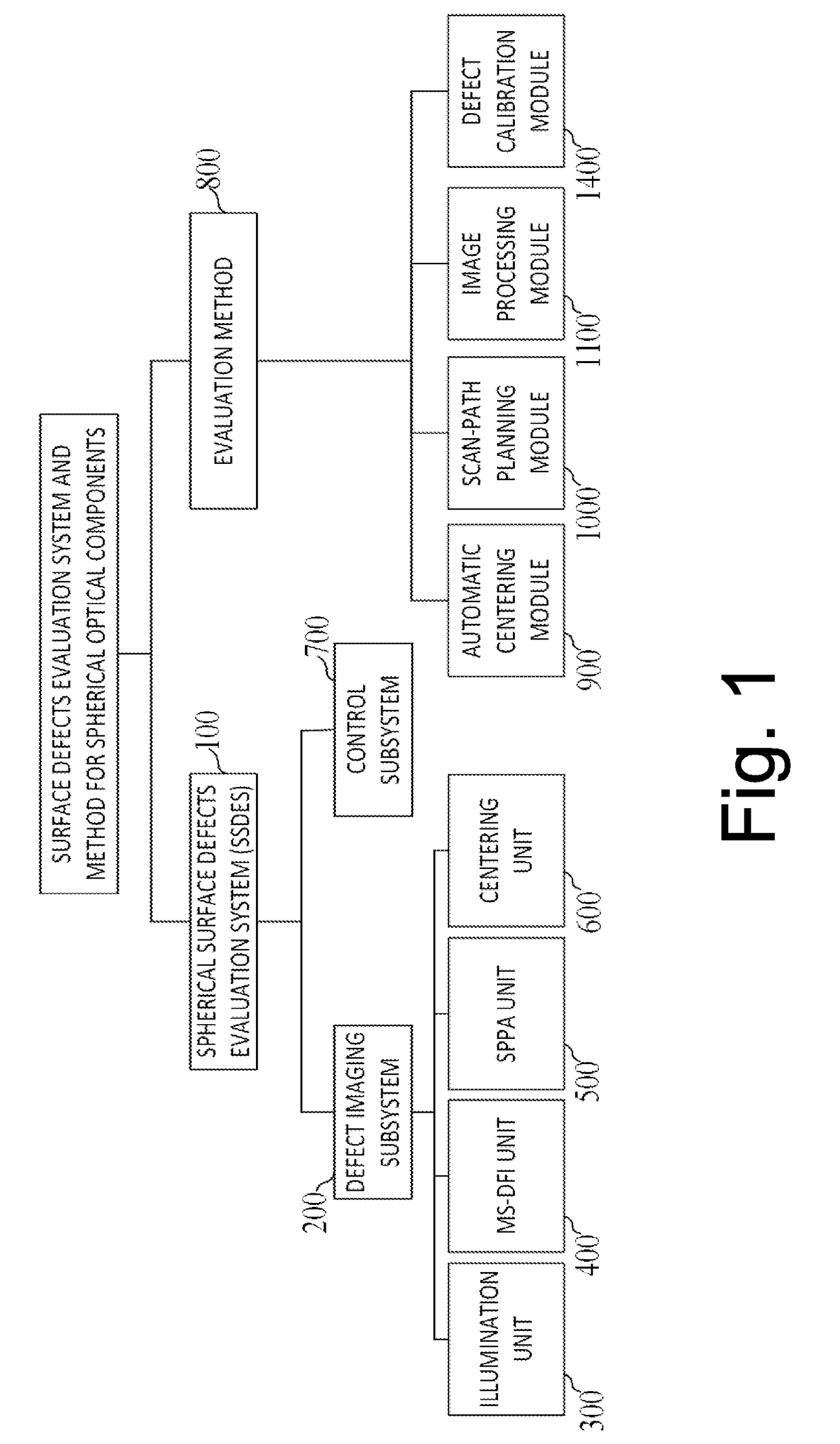
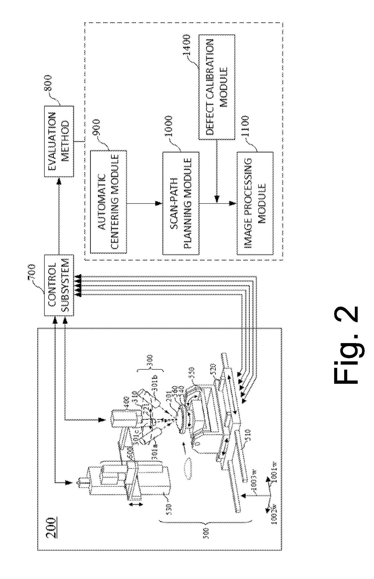
[0117]FIG. 1 illustrates a block diagram of surface defects evaluation system and method for spherical optical components in accordance with the first and the second embodiment of the present invention. The SSDES 100 comprises a defect imaging subsystem 200, a control subsystem 700. The defect imaging subsystem 200 is adapted to acquire microscopic scattering dark-field images suitable for digital image processing. The control subsystem 700 drives the movements of the illumination unit 300, the MS-DFI unit 400, the SPPA unit 500 and the centering unit 600, to acquire images of the inspected surface of the spherical optical component.

[0118]Referring to FIG. 1, the defect imaging subsystem 200 comprises an illumination unit 300, an MS-DFI unit 400, a SPPA unit 500 a...

second embodiment

[0206]Hereafter, a second embodiment of the present invention will be described in detail with reference to FIGS. 26 to 30, which describes surface defects evaluation system and method for concave spherical optical components.

[0207]Surface defects evaluation system and method for concave spherical optical components described in the second embodiment of the present invention is similar to that for convex spherical optical components described in the first embodiment of the present invention. In order to avoid confusion and repetition, parts in FIGS. 26 to 30 which are relevant to parts in FIGS. 1 to 25 are indicated by the same reference numbers. Emphasis in the second embodiment is also put on parts different from the first embodiment.

[0208]FIG. 26 illustrates a schematic diagram of the illumination light path in accordance with the second embodiment of the present invention. The parallel light emitted by the uniform surface light source 320 passes through the lens group 330 and be...

third embodiment

[0212]Hereafter, a third embodiment of the present invention will be described in detail with reference to FIGS. 31 to 33, which describes surface defects evaluation system and method for the small-aperture spherical optical components. Similarly, in order to avoid confusion and repetition, parts in FIGS. 31 to 33 which are relevant to parts in FIGS. 1 to 25 are indicated by the same reference numbers. Emphasis in the third embodiment is also put on parts different from the first embodiment.

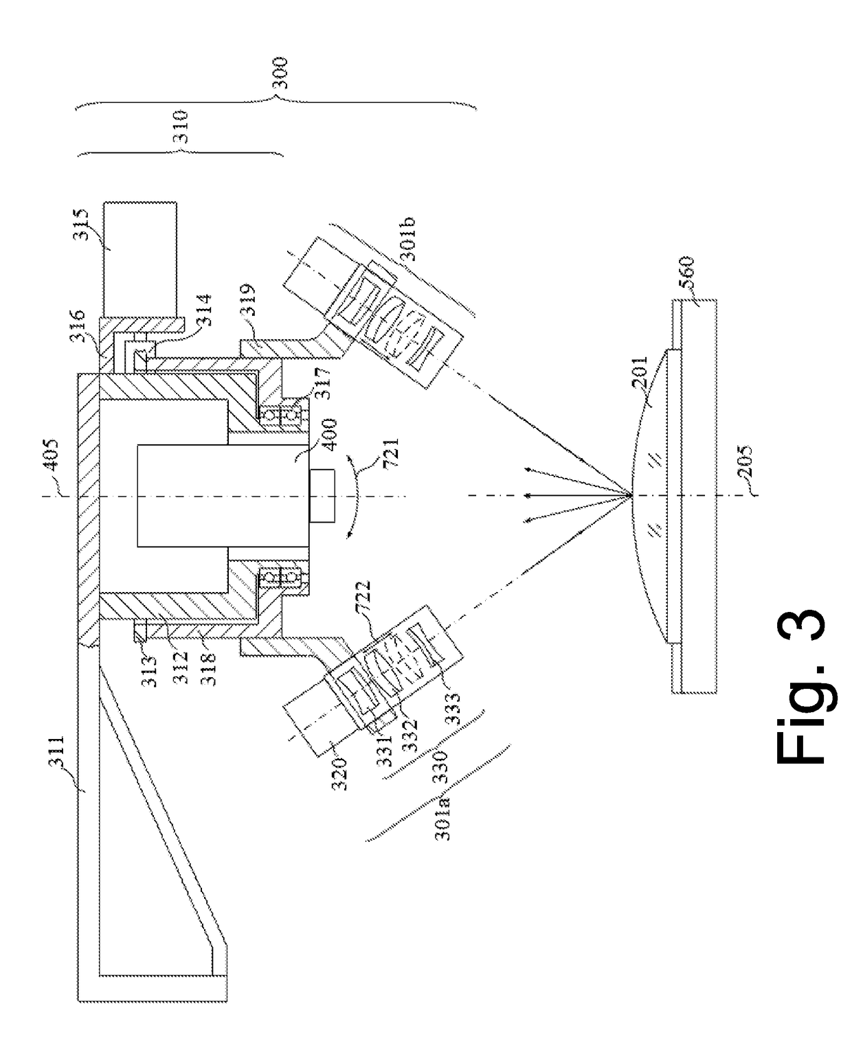
[0213]The small-aperture spherical optical component 1801 is characterized by that its aperture is smaller than the illumination aperture of the illumination unit 300 and the object field of view of the MS-DFI unit 400. Thus, the MS-DFI unit 400 needs to acquire only one sub-aperture located at the vertex of the spherical surface 1009 (as is illustrated in FIG. 15), which is the full-aperture image covering the whole surface of the small-aperture spherical optical components. Referring to FIGS. 3...


PUM

PropertyMeasurementUnit
incident angleaaaaaaaaaa
angleaaaaaaaaaa
incident angleaaaaaaaaaa

Abstract

A defects evaluation system and method are provided in the present invention. Based on the principle of the microscopic scattering dark-field imaging, the present invention implements a sub-aperture scanning for the surface of spherical optical components and then obtains surface defects information with image processing. Firstly, the present invention takes full advantage of the characteristic that the surface defects of spherical optical components can generate scattering light when an annular illumination beam irradiates on the surface, to implement the sub-aperture scanning and imaging that covers the entire spherical surface. Then, a series of procedures such as the global correction of sub-apertures, the 3D stitching, the 2D projection and the digital feature extraction are taken to inspect spherical surface defects. Finally, actual size and position information of defects are evaluated quantitatively with the defects calibration data. The present invention achieves the automatic quantitative evaluation for surface defects of spherical optical components, which considerably enhance the efficiency and precision of the inspection, avoiding the influence of subjectivity on the results. Eventually, reliable numerical basis for the use and process of spherical optical components is provided.

Description

CROSS REFERENCE OF RELATED APPLICATION[0001]This is a U.S. National Stage under 35 U.S.C 371 of the International Application PCT / CN2015 / 089217, filed Sep. 9, 2015, which claims priority under 35 U.S.C. 119(a-d) to CN 201410479580.7, filed Oct. 18, 2014; CN 201510535230.2, filed Aug. 27, 2015; and CN 201510536104.9, filed Aug. 27, 2015.BACKGROUND OF THE PRESENT INVENTIONField of Invention[0002]The present invention belongs to the technical field of machine vision inspection, relating to a defects evaluation system and method for spherical optical components.Description of Related Arts[0003]Spherical optical components are widely used in many optical systems including the large-aperture space telescope, the Inertial Confinement Fusion (ICF) system and the high-power laser system. However, defects such as scratches and digs on the surface of components can not only affect the imaging quality of optical systems, but also generate unnecessary scattering and diffraction light resulting i...

Claims


Application Information

Patent Timeline
Patent Type & Authority Applications(United States)
IPC IPC(8): G01N21/88G01N21/958
CPCG01N21/8806G01N21/958G01N2021/9511G01N2021/9583G01N2021/8822G01N21/8851
Inventor YANG, YONGYINGLIU, DONGLI, YANGCHAI, HUITINGCAO, PINWU, FAN
Owner ZHEJIANG UNIV
Why Eureka
Try Eureka