
Control of intermetallic compound growth in aluminum to steel resistance welding

a technology of resistance spot welding and aluminum workpiece, which is applied in the direction of welding equipment, manufacturing tools, transportation and packaging, etc., can solve the problems of complex ability to cultivate strong weld joints between aluminum workpieces and steel workpieces, and the use of resistance spot welding to joint together workpieces of dissimilar material families has seen less success, so as to achieve low thickness of intermetallic layer, high strength, and high strength

Active Publication Date: 2017-10-19
GM GLOBAL TECH OPERATIONS LLC
View PDF4 Cites 28 Cited by
  • Summary
  • Abstract
  • Description
  • Claims
  • Application Information

AI Technical Summary

Benefits of technology

The patent describes a method for resistance spot welding a workpiece stack-up that includes an aluminum workpiece and an adjacent overlapping steel workpiece. The method involves using reaction-slowing elements to prevent the formation and growth of Fe—Al intermetallic compounds at the weld interface between the two workpieces. The method also involves using an interlayer, such as a rigid shim or a flexible foil, that includes the reaction-slowing elements to further reduce the thickness of the intermetallic layer. The technical effect of this method is to minimize the formation of intermetallic compounds and create a strong and reliable weld joint with reduced thickness of the intermetallic layer.

Problems solved by technology

While resistance spot welding has long been used to join low carbon, low strength steel workpieces to each other, and to some extent aluminum workpieces to each other, the use of resistance spot welding to joint together workpieces of dissimilar material families has seen much less success.
Additionally, the ability to cultivate a strong weld joint between an aluminum workpiece and a steel workpiece is complicated by several factors (1) the presence of a mechanically tough and electrically insulating surface oxide layer on the aluminum workpiece, (2) the several hundred degree difference in the melting points of the aluminum and steel workpieces (steel alloys melt at ˜1500° C., aluminum alloys melt at ˜600° C.

Method used


Image

  • Control of intermetallic compound growth in aluminum to steel resistance welding
  • Control of intermetallic compound growth in aluminum to steel resistance welding
  • Control of intermetallic compound growth in aluminum to steel resistance welding

Examples


Embodiment Construction

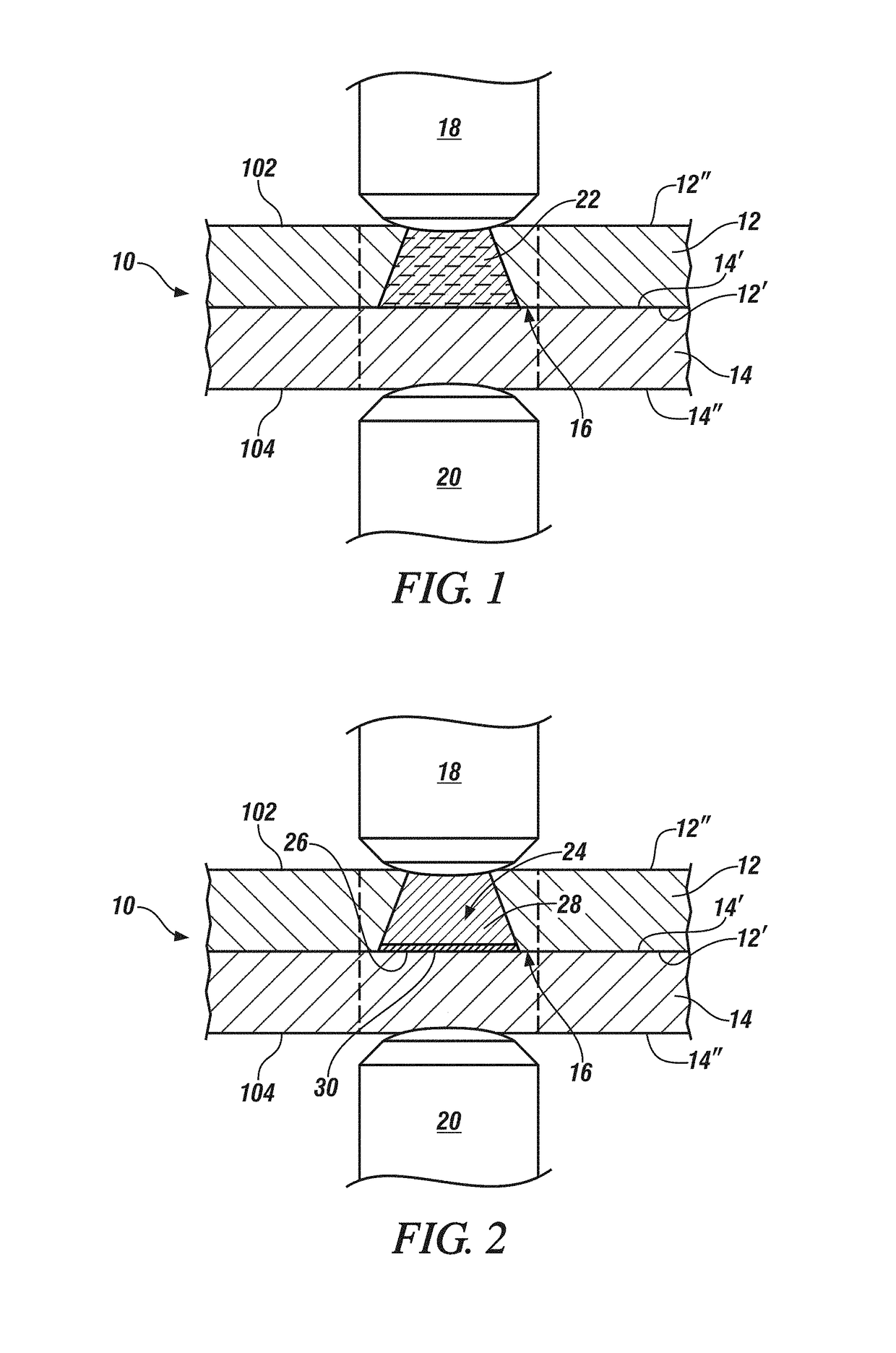
[0024]The present disclosure relates to methods of minimizing the growth rate of iron-aluminum intermetallic compounds when resistance spot welding together an aluminum workpiece and a steel workpiece. Reducing the growth rate of these intermetallic compounds reduces the thickness of the intermetallic layer in the weld joint and results in a weld joint with improved ductility and energy absorption. For instance, in accordance with practices of the present disclosure, the growth rate of Fe—Al intermetallic compounds may be effectively suppressed so that the intermetallic layer that develops within the weld joint adjacent to the steel workpiece has a thickness of 3μm or less, and in many instances 1μm or less, particularly at the perimeter of the weld joint where stresses from applied loads are greatest. The strength of the weld joint in both peel and cross-tension is also enhanced by minimizing the thickness of the intermetallic layer at the perimeter of the weld joint to such an ext...


PUM

PropertyMeasurementUnit
Tensile strengthaaaaaaaaaa
Thicknessaaaaaaaaaa
Flexibilityaaaaaaaaaa

Abstract

A method of resistance spot welding a workpiece stack-up that includes an aluminum workpiece and an overlapping adjacent steel workpiece so as to minimize the thickness of an intermetallic layer comprising Fe—Al intermetallic compounds involves providing reaction-slowing elements at the faying interface of the aluminum and steel workpieces. The reaction-slowing elements may include at least one of carbon, copper, silicon, nickel, manganese, cobalt, or chromium. Various ways are available for making the one or more reaction-slowing elements available at the faying interface of the aluminum and steel workpieces including being dissolved in a high strength steel or being present in an interlayer that may take on a variety of forms including a rigid shim, a flexible foil, a deposited layer adhered to and metallurgically bonded with a faying surface of the steel workpiece, or an interadjacent organic material layer that includes particles containing the reaction-slowing elements.

Description

CROSS-REFERENCE TO RELATED APPLICATION(S)[0001]This application claims the benefit of U.S. Provisional Application Nos. 62 / 322,360 filed on Apr. 14, 2016 and 62 / 323,256 filed on Apr. 15, 2016. The entire contents of each the aforementioned provisional applications are incorporated herein by reference.TECHNICAL FIELD[0002]This disclosure pertains generally to resistance spot welding of an aluminum workpiece to a steel workpiece and, more specifically, to spot welding practices in which elements that slow the growth of aluminum- and iron-containing intermetallic compounds are introduced at the faying interface of the aluminum and steel workpieces to thereby increase the ductility and energy absorption of a weld joint formed between the aluminum and steel workpieces by way of resistance spot welding.INTRODUCTION[0003]There is continuing interest in reducing the mass of vehicles. This goal, coupled with the need to maintain strength and stiffness, has led to the adoption of higher stren...

Claims


Application Information

Patent Timeline
IPC IPC(8): B23K11/20C22C38/04C22C38/02B23K35/36B23K11/18B23K11/11B23K35/30B23K35/02B23K35/00C22C38/16B23K103/04B23K103/10B23K103/20
CPCB23K11/20B23K11/115B23K11/185B23K35/002B23K35/004B23K35/0294B23K2203/04B23K35/3612C22C38/16C22C38/04C22C38/02B23K2203/20B23K2203/10B23K35/3053B23K11/11B23K11/34B23K2103/20B23K11/163B23K2101/006B23K2101/18B23K2101/34B23K2101/35B23K2103/04B23K2103/10
Inventor BROWN, TYSON W.SIGLER, DAVID R.CARLSON, BLAIR E.HASELHUHN, AMBERLEE S.
Owner GM GLOBAL TECH OPERATIONS LLC
Learn More