Energy storage device with encapsulation anchoring

a technology of energy storage and anchoring, which is applied in the direction of primary cells, vacuum evaporation coatings, sputtering coatings, etc., can solve the problems of minimal cell edge surface area available, adverse impact on battery cell performance, and encapsulation layer may lift along, so as to promote the anchoring of the encapsulant therein

Inactive Publication Date: 2017-10-19
APPLIED MATERIALS INC
View PDF0 Cites 4 Cited by
  • Summary
  • Abstract
  • Description
  • Claims
  • Application Information

AI Technical Summary

Benefits of technology

[0008]In view of the foregoing, approaches herein provide improved encapsulation of an energy storage device. In one approach, a thin film storage device stack is formed atop a first side of a substrate, and an encapsulant is formed over the thin film storage device stack. Prior to formation of the encapsulant, a recess may be formed in the substrate adjacent the thin film storage device stack, wherein the encapsulant extends into the recess. In some approaches, the recess is provided partially through a depth of the substrate, and has a geometry to promote anchoring of the encapsulant therein.

Problems solved by technology

During a battery cell charge and discharge cycle, the encapsulation layer may lift along cell edges due to a combination of laser edge cutting heat affect zone (HAZ) and poor encapsulation layer adhesion along the cell edges.
Such cell edge delamination leads to the premature introduction of unwanted moisture and gas penetration, resulting in an adverse impact to the battery cell performance.
This leaves minimal cell edge surface area available for lateral encapsulation protection and, as a result, the moisture penetration lateral pathway is short.

Method used


Image

  • Energy storage device with encapsulation anchoring
  • Energy storage device with encapsulation anchoring
  • Energy storage device with encapsulation anchoring

Examples


Embodiment Construction

[0026]One or more approaches in accordance with the present disclosure will now be described more fully hereinafter with reference to the accompanying drawings, where embodiments of devices and methods are shown. The approaches may be embodied in many different forms and are not to be construed as being limited to the embodiments set forth herein. Instead, these embodiments are provided so this disclosure will be thorough and complete, and will fully convey the scope of the devices and methods to those skilled in the art.

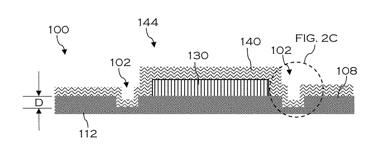
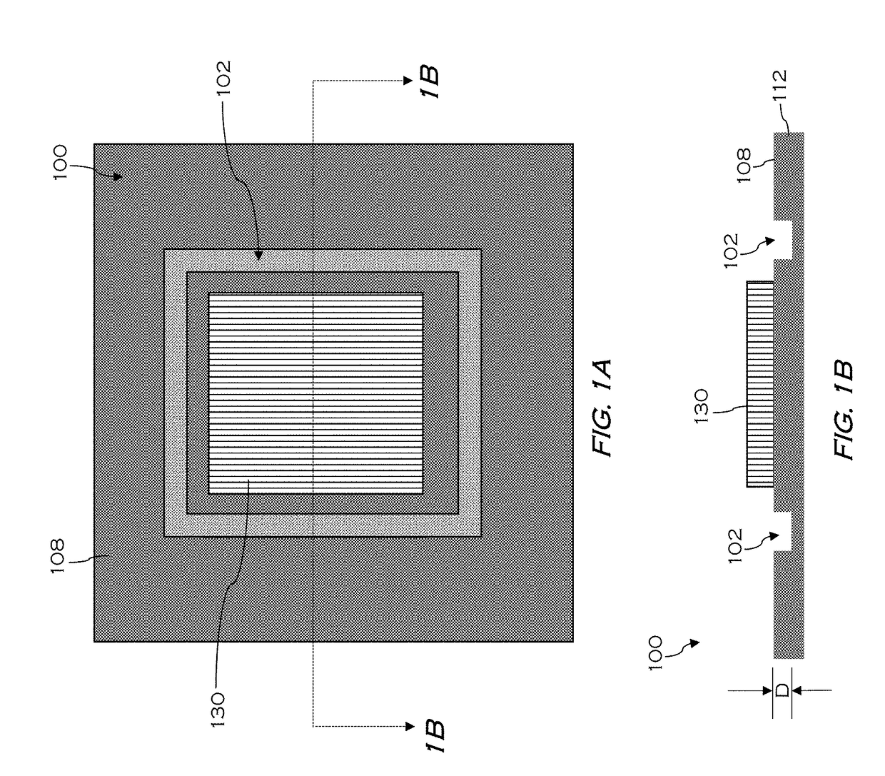
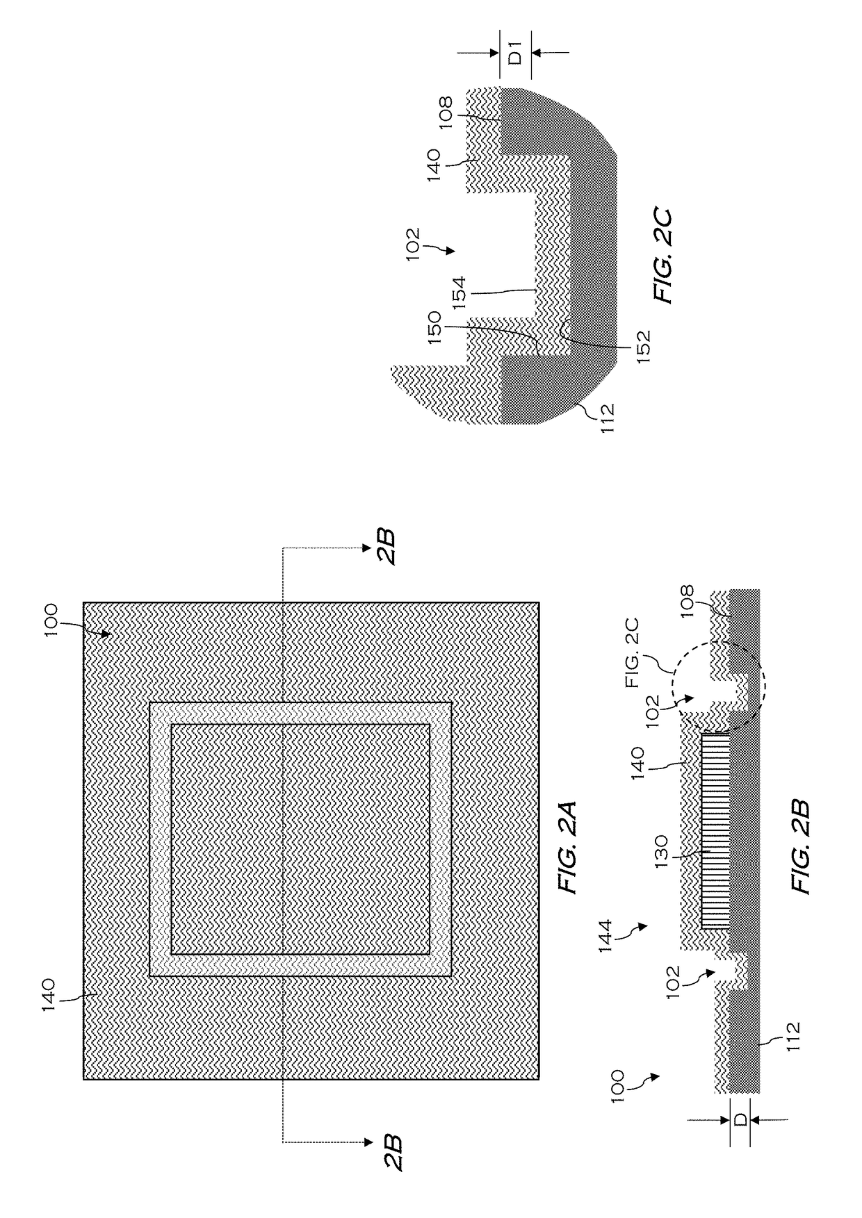
[0027]For the sake of convenience and clarity, terms such as “top,”“bottom,”“upper,”“lower,”“vertical,”“horizontal,”“lateral,” and “longitudinal” will be used herein to describe the relative placement and orientation of these components and their constituent parts, each with respect to the geometry and orientation of the micro battery as appearing in the figures. The terminology will include the words specifically mentioned, derivatives thereof, and words of similar...


PUM

PropertyMeasurementUnit
thickaaaaaaaaaa
thickaaaaaaaaaa
thicknessaaaaaaaaaa

Abstract

Approaches herein provide improved encapsulation of an energy storage device. In one approach, a thin film storage device stack is formed atop a first side of a substrate, and an encapsulant is formed over the thin film storage device stack. A recess formed in the substrate adjacent the thin film storage device stack provides an anchoring point for the encapsulant. In some approaches, the recess is provided partially through a depth of the substrate, and has a geometry to promote physical coupling between the encapsulant and the substrate.

Description

RELATED APPLICATIONS[0001]This Application claims priority to U.S. provisional patent application No. 62 / 322,415, filed Apr. 14, 2016, entitled “Volume Change Accommodating TFE Materials” and incorporated by reference herein in its entirety.FIELD[0002]The present embodiments relate to thin film encapsulation (TFE) technology used to protect active devices and, more particularly, to an energy storage device with an anchored encapsulant.BACKGROUND[0003]Thin film encapsulation (TFE) technology is often employed in devices where the devices are purely electrical devices or electro-optical devices, such as Organic Light Emitting Diodes (OLED). Other than possibly experiencing a generally small global thermal expansion from heat generation during the device operation, these electrical devices and electro-optical devices do not exhibit volume changes during operation, since just electrons and photons are transported within the devices during operation. Such global effects due to global the...

Claims


Application Information

Patent Timeline
Patent Type & Authority Applications(United States)
IPC IPC(8): H01M2/08H01M2/02H01M4/38H01M4/525H01M50/11H01M50/117H01M50/119
CPCH01M2/08H01M4/525H01M2300/0068H01M2/026H01M2/0287H01M4/382H01M10/052H01M10/0585H01J37/32715H01J37/3426H01M2300/0065Y02E60/10Y02P70/50H01M50/11H01M50/117H01M50/119B23K2101/34B23K2101/36B23K2103/172Y02T10/70H01M50/24H01M50/124H01M10/0525H01M2220/30H01M10/0436B23K26/142B23K26/0006B23K26/362B29C59/16B29K2995/0006B29L2031/3468H01M6/005H01M6/18H01M6/40C23C14/34C23C14/50H01M6/188
Inventor YOUNG, MICHAEL YU-TAKFRANKLIN, JEFFREY L.KWAK, BYUNG-SUNG
Owner APPLIED MATERIALS INC
Why Eureka
Try Eureka