
Photoirradiation device, photoreaction method using the same, and method for producing lactam

Inactive Publication Date: 2017-10-26
TORAY IND INC
View PDF0 Cites 6 Cited by
  • Summary
  • Abstract
  • Description
  • Claims
  • Application Information

AI Technical Summary

Benefits of technology

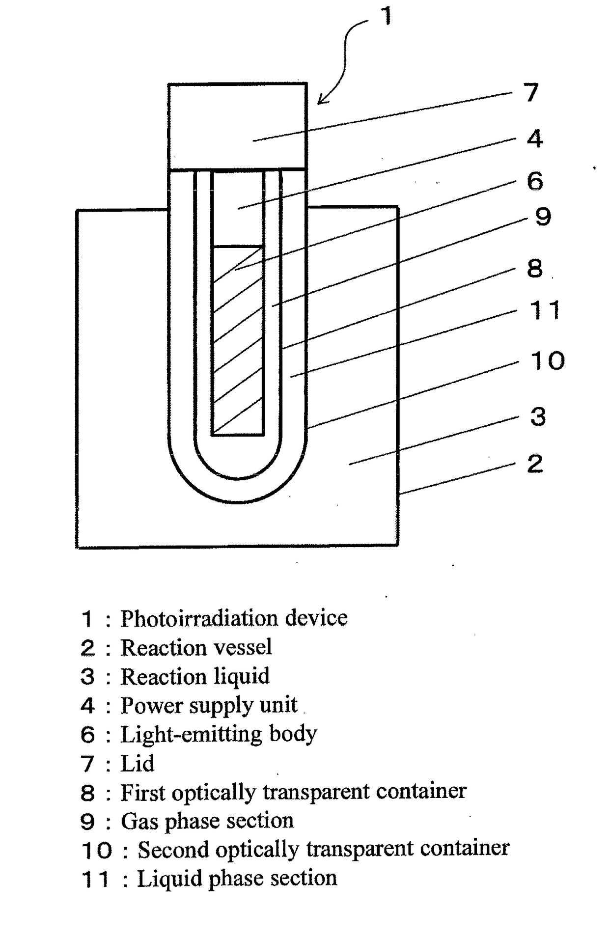
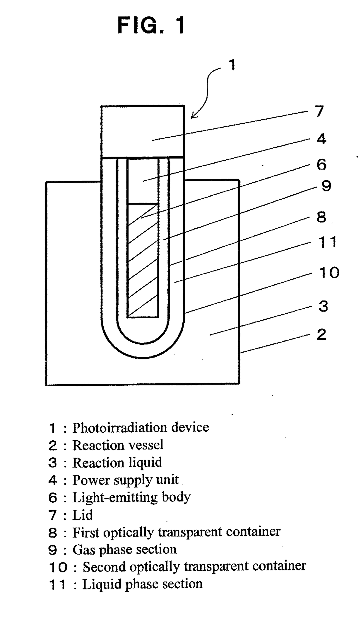
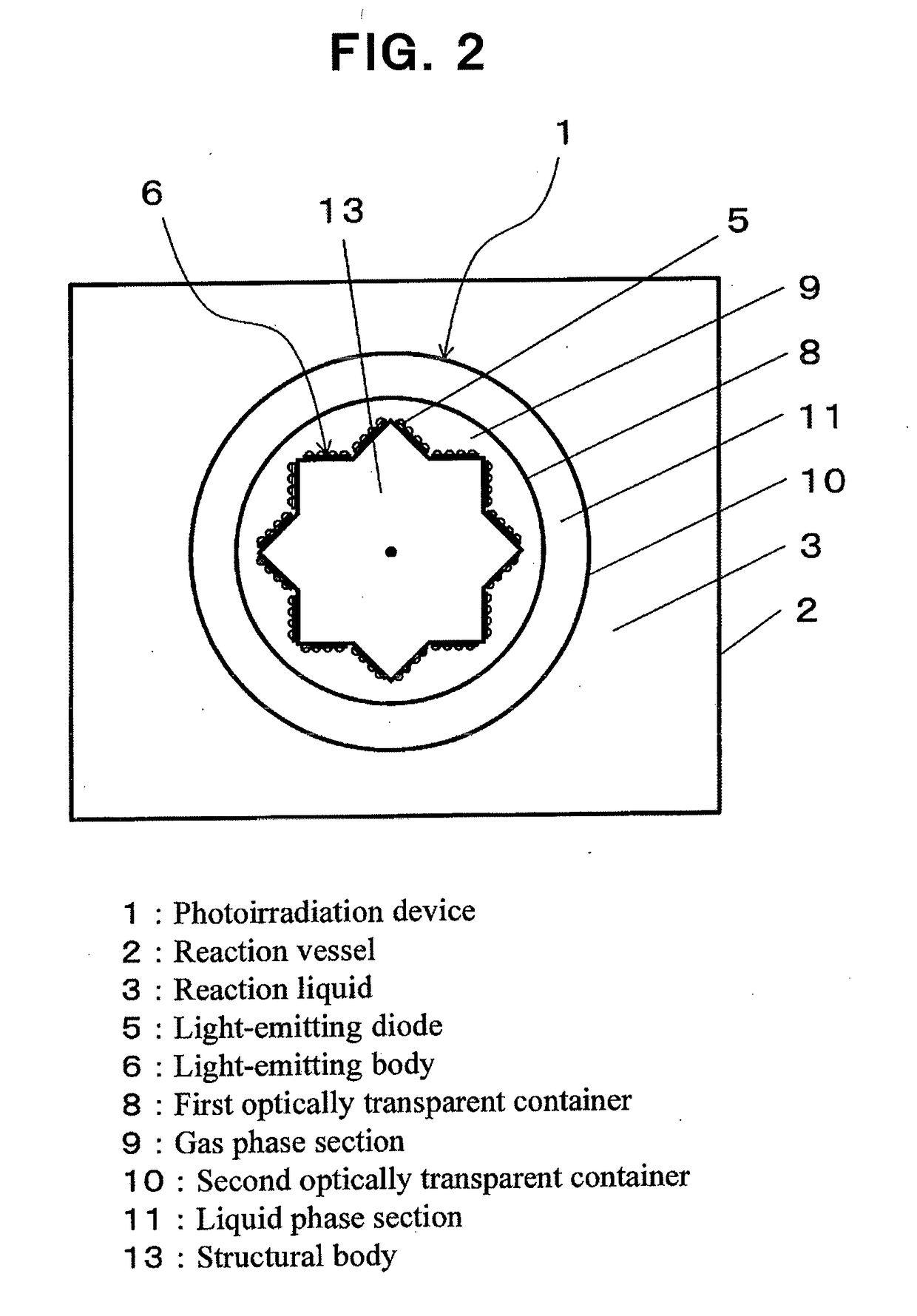
The present invention proposes a photoirradiation device that can efficiently use light emitted from an LED light source, in a linear and effective manner. However, there are problems of light obstruction and reflection when a target liquid is a flammable liquid. To solve this, the invention proposes the use of an optically transparent container with a specific refractive index liquid phase section to suppress the reflection of light and increase the optical transparency of the device. The invention is useful for photoreactions, especially for producing cycloalkanone oxime and lactam.

Problems solved by technology

However, in the inventions disclosed in these Patent documents 1 and 2, it cannot be said that a structure of a photoirradiation device capable of necessarily and effectively utilizing light linearly emitted from a light emitting diode is proposed.
Further, if a photoreaction is aimed, in most case a target liquids is a flammable liquid, physical separation between the photoirradiation device as an ignition source and the target liquid is essential, however, in the inventions disclosed in Patent documents 1 and 2, there is a problem that light is obstructed by reflection by an obstacle for the separation provided in the photoirradiation route, that is, an optically transparent container, and the rate of the light transmission is reduced.

Method used


Image

  • Photoirradiation device, photoreaction method using the same, and method for producing lactam
  • Photoirradiation device, photoreaction method using the same, and method for producing lactam
  • Photoirradiation device, photoreaction method using the same, and method for producing lactam

Examples


example 1

, Reference Example 1

[0060]For the light emitting body using light emitting diodes as a light source, borosilicate glass with a refractive index of 1.49 was used for the first optically transparent container, the gas phase section was formed from N2, and water was placed in the liquid phase section covering the first optically transparent container, and the transmittance of light (optical transparency) from the first optically transparent container to the liquid phase section, in case where the incident angle from the first optically transparent container to the interface between the container outer surface and the liquid phase section was changed, was calculated. As the results are shown in Table 1, high transmittance was obtained. In case where water was placed in the liquid phase section, total reflection occurred at an incident angle of 70 degrees or more (Reference Example 1).

example 2

[0063]With respect to the light emitting body using light emitting diodes as a light source, N2 was used for the gas phase section covering the light emitting diodes, and borosilicate glass with a refractive index of 1.49 was used for the first optically transparent container. The incident angle of the light on the optical axis of the light emitting diodes from the gas phase section to the inner surface of the first optically transparent container was set at 10°, and the transmittance of light from the gas phase section to the first optically transparent container was calculated. The results are shown in Table 2.

examples 3 to 9

[0064]The optical transparency (transmittance of light) was calculated in the same manner as in Example 2 other than a condition where the incident angle was changed from 20° to 80°. The results are shown in Table 2.

TABLE 2RefractiveIncidentside mediumOpticalside mediumOpticallytransparency fromGas phasetransparentgas phase section toIncident angle from gassectioncontainerfirst opticallyphase section to innerRefractiveRefractiveReflectancetransparentsurface of container (°)MaterialindexMaterialindex(—)container (—)Example 210N21.00borosilicate1.490.0390.9613Example 320glass0.0390.9610Example 4300.0400.9598Example 5400.0440.9556Example 6500.0560.9438Example 7600.0880.9125Example 8700.1690.8308Example 9800.3860.6140

[0065]The photoirradiation device according to the present invention is applicable to any field in which efficient photoirradiation is desired, and in particular, it is suitable to a photoreaction method using the photoirradiation device and a method for producing a lactam ...


PUM

PropertyMeasurementUnit
Fractionaaaaaaaaaa
Angleaaaaaaaaaa
Compositionaaaaaaaaaa

Abstract

Provided are a photoirradiation device equipped with: a first optically transparent container for covering a light-emitting body provided with light-emitting diodes; a liquid phase section provided on the outside thereof and formed from a liquid having a refractive index closer to that of the first optically transparent container than that of a gas forming a gas phase section inside the first optically transparent container; and a second optically transparent container for covering the liquid phase section, a photoreaction method using the photoirradiation device, and a method for producing lactam by using the photoreaction method. The reflection of light between a target liquid and a light-emitting diode light source is suppressed, and a desired photoirradiation can be achieved with a high optical transparency.

Description

CROSS REFERENCE TO RELATED APPLICATIONS[0001]This is the U.S. National Phase application of PCT / JP2015 / 076415, filed Sep. 17, 2015, which claims priority to Japanese Patent Application No. 2014-208067, filed Oct. 9, 2014, the disclosures of each of these applications being incorporated herein by reference in their entireties for all purposes.TECHNICAL FIELD OF THE INVENTION[0002]The present invention relates to a photoirradiation device using light-emitting diodes as a light source, a photoreaction method using the photoirradiation device, and a method for producing a lactam by using the photoreaction method.BACKGROUND OF THE INVENTION[0003]A photoreaction is also called a photochemical reaction, and indicates the whole of chemical reactions each in which molecules are brought into a state having a high energy level, that is, a so-called excited state by photoirradiation, namely by making a radical reaction initiator absorb energy ascribed to the irradiated light, and the reaction i...

Claims


Application Information

Patent Timeline
IPC IPC(8): C07D201/04B01J19/12C07C249/06
CPCC07D201/04B01J19/127B01J2219/0877B01J2219/1203C07C249/06B01J19/12C07B61/00C07C251/44C07D225/02F21K9/00F21V3/00F21Y2107/30F21Y2115/10
Inventor UCHIUMI, RYOTATAKAHASHI, TORU
Owner TORAY IND INC
Learn More