Filter for extruder press

a filter and extruder press technology, applied in the direction of filtration separation, presses, separation processes, etc., can solve the problems of difficult control of the filtering process, high cost of required equipment, and difficulty in separating solids from liquids effectively under pressure with conventional equipment,

Active Publication Date: 2017-11-02
GREENFIELD SPECIALTY ALCOHOLS
View PDF0 Cites 4 Cited by
  • Summary
  • Abstract
  • Description
  • Claims
  • Application Information

AI Technical Summary

Benefits of technology

[0015]It is an object of the present invention to obviate or mitigate at least one disadvantage of previous solid / liquid separation devices and processes.

Problems solved by technology

It is difficult with conventional equipment to effectively separate solids from liquid under pressure and especially the high temperature and pressure conditions required for cellulose pre-treatment.
High separating pressures unfortunately require strong filter media, which are able to withstand the separating pressure within the press, making control of the filtering process difficult and the required equipment very costly.
The thicker the pressure jacket, the longer the drainage perforations, the higher the flow resistance through the perforations and the higher the risk of clogging.
However, increasing the number of perforations weakens the pressure jacket, once again reducing the pressure capacity of the filter unit.
However, this will limit the capacity of the filter to retain small solids, or may lead to increased clogging problems.
Thus, the acceptable pore size of the filter is limited by the size of the fibers and particles to be retained in the solids fraction.
The clarity of the liquid fraction is limited solely by the pore size of the filter media and pores that are too large reduce the liquid / solid separation efficiency and potentially lead to plugging of downstream equipment.
However, once a filter becomes plugged, it takes a pressure higher than the operating pressure to backwash the media.
This can become problematic when working with filter media operating at pressures above 1000 psig in a process that is to be continuous to maximize the production rate, for example to obtain high cellulose pre-treatment process efficiency.
However, most backwashing requires interruption of the filtering operations, so that increased backwashing reduces the production rate.
Conventional single, twin, or triple screw extruders do not have the residence time necessary for pre-treatment of biomass, and also do not have useful and efficient solid / fluid separating devices for the pre-treatment of biomass, in particular lignocellulosic biomass.
Operating pressures of such a screw press are low, due to the low strength of the perforated casing.
Moreover, drilling perforations in a housing or press jacket is associated with serious challenges when very small apertures are desired for the separation of fine solids.
The need for a backer plate for each filter plate limits the filter porosity, since the axial length of the module represented by the cumulative thickness of the backer plates cannot be used for filtering.
Moreover, the use of a filter slot in combination with a drainage passage in the backer plate results in a long, tortuous path of the separated fluids with elevated backpressure and ample opportunity for fines accumulations in the slot and / or the passage.
However, clogging of the filter passage with fines is still possible and removal of such clogging may prove challenging due to the long filter passage.
Clogging of the filter passage with particulates occurs due to the long filter passage extending from the core opening to the outside of the filter block.
The length of the filter passage also makes, removal of such clogging challenging and backwashing is difficult due to significant backpressure.
Moreover, backwashing of a clogged filter block requires the draining of the separated fluids from the collection chamber, supplying backwashing fluid into the chamber and removing the backwashing fluid upon completion of the backwash cycle.
This creates significant down time and cost.

Method used


Image

  • Filter for extruder press
  • Filter for extruder press
  • Filter for extruder press

Examples


Embodiment Construction

[0074]It will be appreciated that for simplicity and clarity of illustration, where considered appropriate, reference numerals may be repeated among the figures to indicate corresponding or analogous elements or steps. In addition, numerous specific details are set forth in order to provide a thorough understanding of the exemplary embodiments described herein. However, it will be understood by those of ordinary skill in the art that the embodiments described herein may be practiced without these specific details. In other instances, well-known methods, procedures and components have not been described in detail so as not to obscure the embodiments described herein. Furthermore, this description is not to be considered as limiting the scope of the embodiments described herein in any way, but rather as merely describing the implementation of the various embodiments described herein.

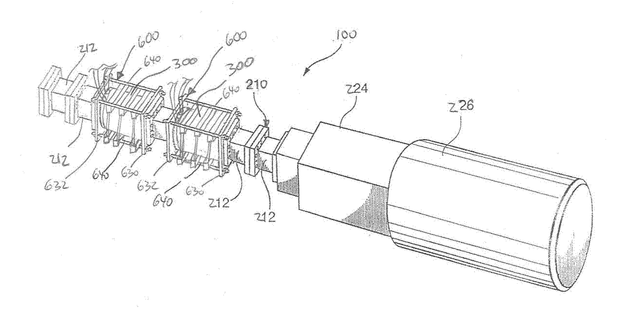
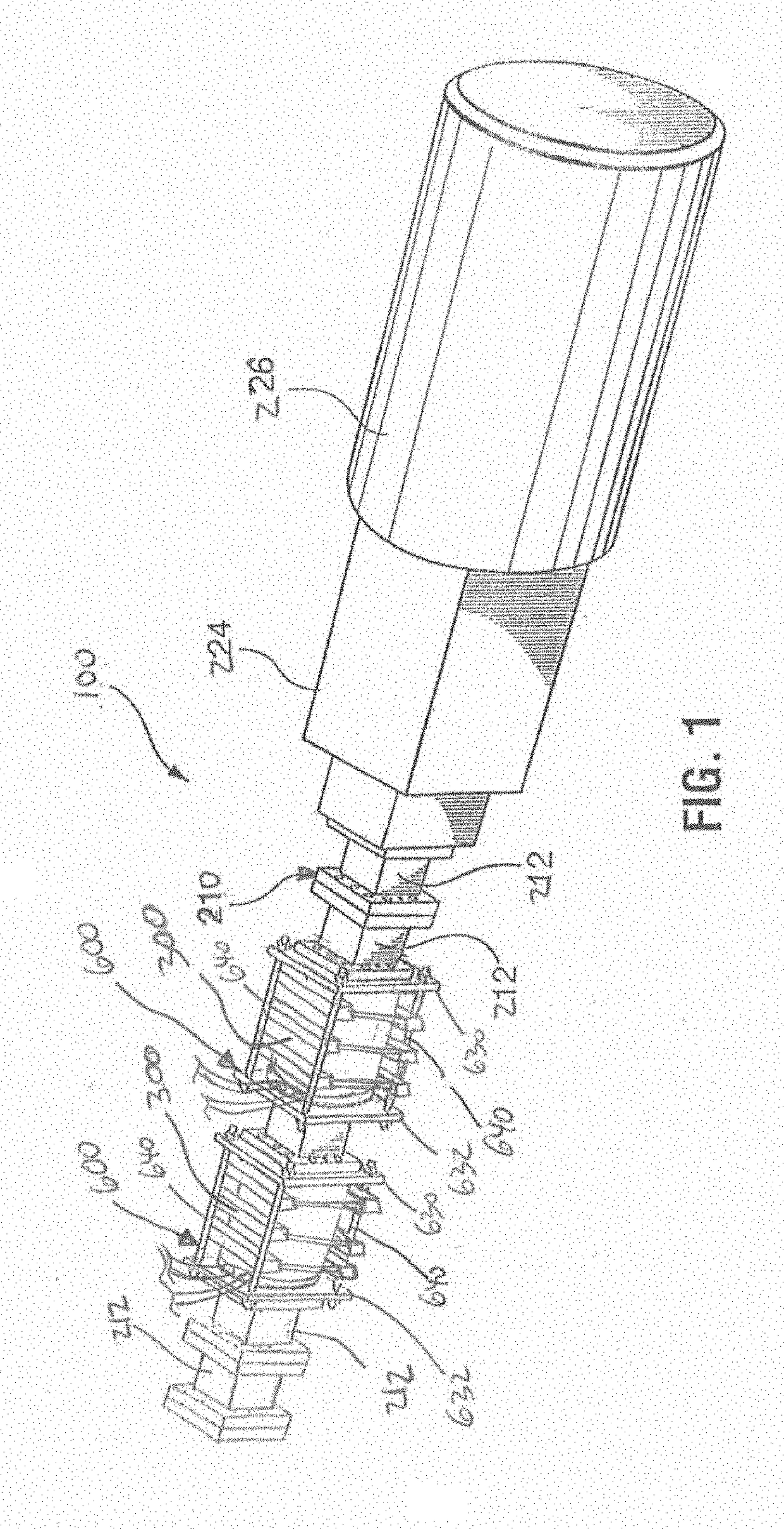
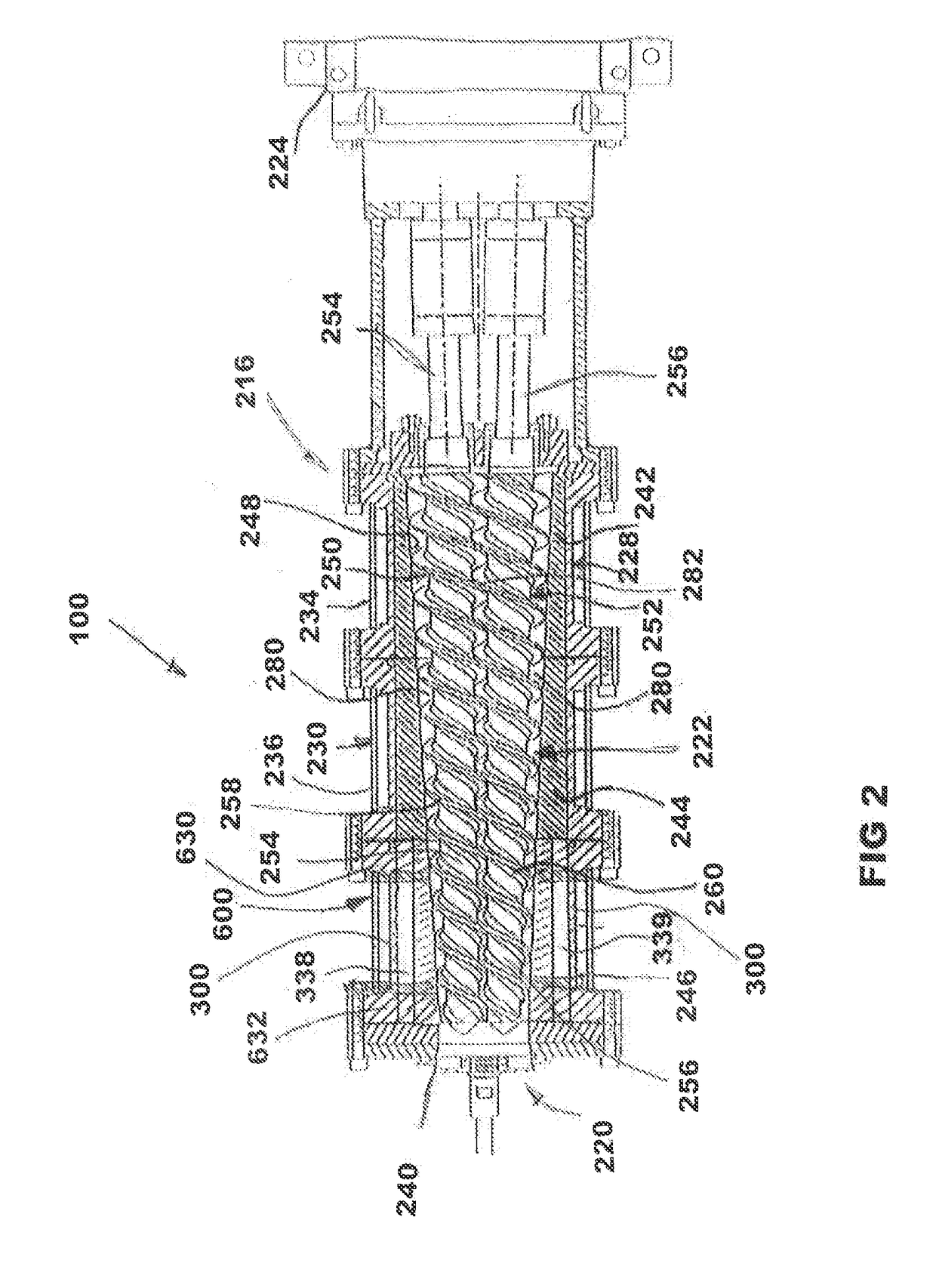
[0075]The solid / fluid separation module of the invention is intended for use with a single screw, twin ...


PUM

PropertyMeasurementUnit
pressuresaaaaaaaaaa
pressuresaaaaaaaaaa
pore sizeaaaaaaaaaa

Abstract

A solid/fluid separation module and press enables treatment of solids with enclosed fluids to generate a filtered mass having a solids content above 50%. A split filter module with first and second filter blocks clamped together for forming barrel sections or filtering sections is disclosed for use in a solid/fluid separating device including a barrel and a conveyor screw in the barrel. The split filter module permits replacement, maintenance, or repair of the filter blocks without disassembly or the separating device, or removal of the conveyor screws.

Description

[0001]This application claims the benefit of priority from U.S. Provisional Patent Application No. 62 / 330,444, filed May 2, 2016, the entire contents of which are incorporated by reference.FIELD OF THE INVENTION[0002]The present disclosure is broadly concerned with solid / fluid separation devices and methods for the separation of different types of solid / fluid mixtures.BACKGROUND OF THE INVENTION[0003]Solid / fluid or solid / liquid separation is necessary in many commercial processes, for example biomass processing, food processing (oil extraction), reduction of waste stream volume in wet extraction processes, dewatering processes, or suspended solids removal.[0004]Many biomass treatment processes generate a wet fiber slurry from which dissolved compounds, gases and / or liquids must be separated at various process steps to isolate a solids and / or fibrous portion. Solid / fluid separation is generally done by filtration and either in batch operation, with filter presses, or continuously by ...

Claims


Application Information

Patent Timeline
Patent Type & Authority Applications(United States)
IPC IPC(8): B01D25/12B30B9/12B01D25/32
CPCB01D25/12B30B9/124B01D25/325B30B9/16B30B9/262B30B9/26B30B9/12
Inventor BRADT, CHRISTOPHER BRUCE
Owner GREENFIELD SPECIALTY ALCOHOLS
Why Eureka
Try Eureka