Control apparatus for internal combustion engine

a control apparatus and internal combustion engine technology, applied in the direction of electric control, combustion engines, machines/engines, etc., can solve the problems of deterioration of combustion fluctuation, inability to perform correct fuel injection amount by feedback control, and difficulty in performing appropriate combustion control, so as to improve controllability of slightly stratified-charge lean burn, the effect of reducing the difficulty of ignitability

Active Publication Date: 2017-11-02
TOYOTA JIDOSHA KK
View PDF1 Cites 16 Cited by
  • Summary
  • Abstract
  • Description
  • Claims
  • Application Information

AI Technical Summary

Benefits of technology

[0021]According to the control apparatus for an internal combustion engine of the present disclosure, during the slightly stratified-charge lean-burn operation, the compression stroke injection amount is controlled on the basis of the ignition delay index value. In the slightly stratified-charge lean-burn operation, the compression stroke injection for forming a stratified mixture has a greater impact on the ignitability of the air-fuel mixture compared to the main injection for forming a homogeneous mixture. According to the control of the compression stroke injection amount of the present disclosure, the control of the fuel injection amount for obtaining a proper ignitability (that is, a proper ignition delay) can be effectively performed for the compression stroke injection amount that has a greater impact on the ignitability. Further, according to the control apparatus of the present disclosure, the main injection amount is controlled on the specified combustion index value that represents a main c

Problems solved by technology

That is, if a correction to make the actual crank angle interval approach the target crank angle interval is caused to be reflected in both of the fuel amount by the main injection and the fuel amount by the compression stroke injection, it may become difficult to perform an appropriate combustion control with taking into consideration the characteristics of the respective fuel injections described above.
For example, if the fuel injection amount for forming the stratified mixture (that is, the amount of fuel by the compression stroke injection) is appropriate and the fuel injection amount for forming the homogene

Method used


Image

  • Control apparatus for internal combustion engine
  • Control apparatus for internal combustion engine
  • Control apparatus for internal combustion engine

Examples


first embodiment

[0043]Firstly, a first embodiment of the present disclosure will be described with reference to FIGS. 1 to 7.

[System Configuration of First Embodiment]

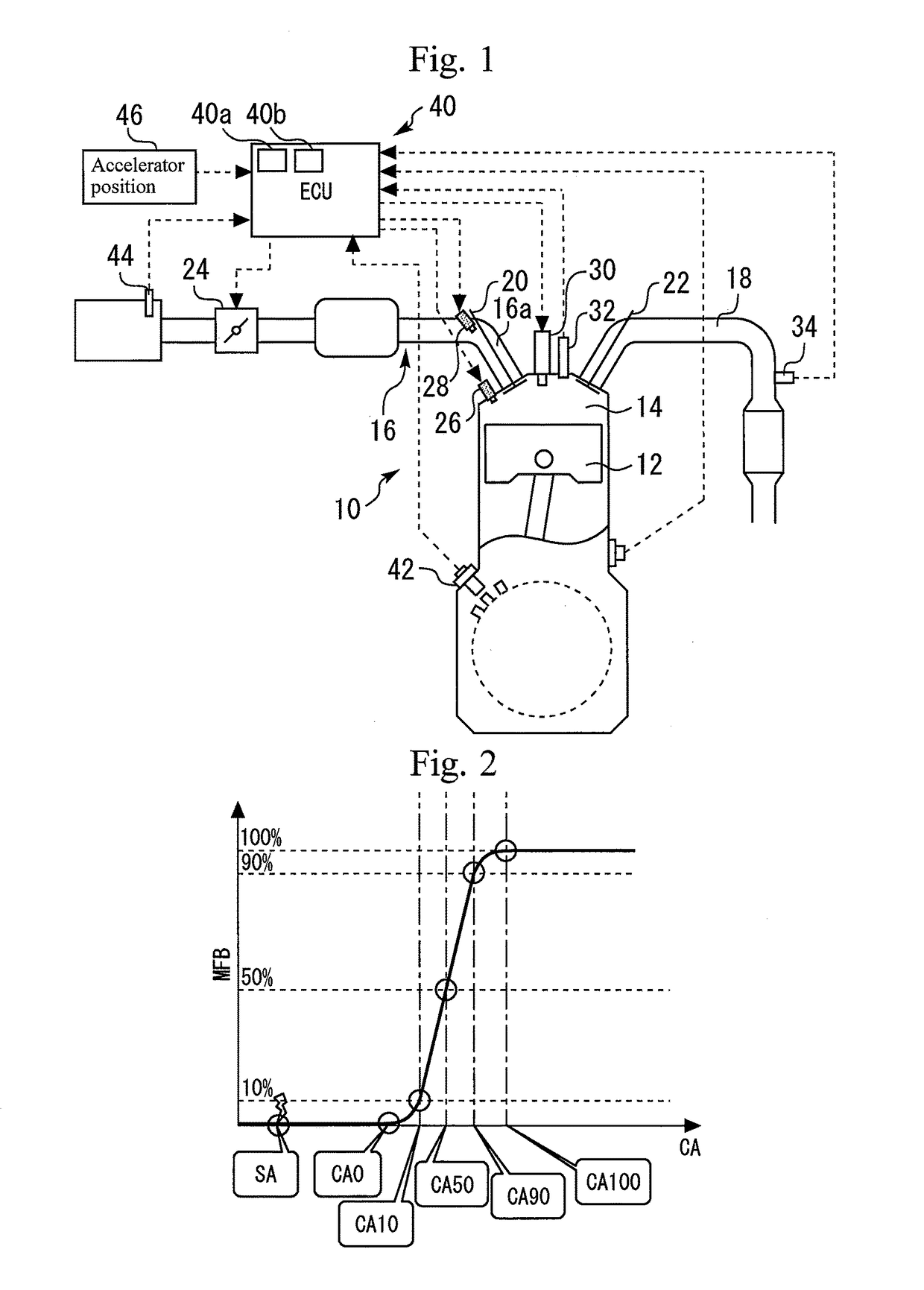
[0044]FIG. 1 is a view for describing a system configuration according to the first embodiment of the present disclosure. The system shown in FIG. 1 includes a spark-ignition type internal combustion engine (as an example, gasoline engine) 10. A piston 12 is provided in each cylinder of the internal combustion engine 10. A combustion chamber 14 is formed at the top side of the piston 12 inside the respective cylinders. An intake channel 16 and an exhaust channel 18 communicate with the combustion chamber 14.

[0045]An intake valve 20 is provided in an intake port 16a of the intake channel 16. The intake valve 20 opens and closes the intake port 16a. An exhaust valve 22 is provided in an exhaust port of the exhaust channel 18. The exhaust valve 22 opens and closes the exhaust port. An electronically controlled throttle valve 24 is provid...

second embodiment

[0086]Next, a second embodiment of the present disclosure will be described with reference to FIG. 8. In the following explanation, it is assumed that the configuration shown in FIG. 1 is used as an example of the configuration of a system according to the second embodiment. This also applies to third to eighth embodiments described later.

[Control According to Second Embodiment]

[0087]The control according to the present embodiment is different from the control according to the first embodiment described above in terms of the calculation method of the compression stroke injection amount based on the SA-CA10. To be more specific, in the first embodiment, the value that is obtained by adding, to the basic compression stroke injection amount FCB, the compression stroke injection correction term FCC by the SA-CA10 feedback control is calculated as a final compression stroke injection amount. In contrast, in the present embodiment, the basic compression stroke injection amount FCB is obta...

third embodiment

Control

[0093]The control according to the present embodiment is different from the control according to the first embodiment descried above in terms of the manner of controlling the intake stroke injection amount based on the CA10-90. More specifically, in the present embodiment, the CA10-90 feedback control described below is performed instead of a CA10-90 correction control described above.

(CA10-90 Feedback Control)

[0094]According to the CA10-90 feedback control, the intake stroke injection amount is controlled so that the actual CA10-90 based on the output values of the in-cylinder pressure sensor 32 approaches a target CA10-90. To be more specific, according to the CA10-90 feedback control, for a combustion cycle in which the actual CA10-90 that is smaller than the target CA10-90 is obtained (that is, in which the actual main combustion speed is higher than a target main combustion speed), correction to decrease, from the basic intake stroke injection amount, the intake stroke i...


PUM


Abstract

A control apparatus for an internal combustion engine is configured, during a slightly stratified-charge lean-burn operation, to: calculate a basic total fuel injection amount based on a required torque; calculate a compression stroke injection amount based on an ignition delay index value; calculate, as a basic main injection amount, a value obtained by subtracting a compression stroke injection amount from the basic total fuel injection amount; calculate, based on an output value of an in-cylinder pressure sensor, an actual specified combustion index value that represents a main combustion speed or a combustion fluctuation rate; calculate a main injection correction term based on a result of a comparison between a target specified combustion index value or a tolerable specified combustion index value, and the actual specified combustion index value; and calculate a main injection amount by adding the main injection correction term to the basic main injection amount.

Description

CROSS-REFERENCE TO RELATED APPLICATION[0001]This application is based on and claims the benefit of Japanese Patent Application No. 2016-089760, filed on Apr. 27, 2016, which is incorporated by reference herein in its entirety.BACKGROUNDTechnical Field[0002]The present disclosure relates to a control apparatus for an internal combustion engine.Background Art[0003]JP 2015-094339A, for example, discloses a control apparatus for an internal combustion engine that includes an in-cylinder pressure sensor. In this control apparatus, feedback control for fuel injection amount with output values of the in-cylinder pressure sensor is executed in such a manner that an actual crank angle interval from a spark timing to a crank angle having a certain mass fraction of burned fuel approaches a target crank angle interval. In addition, in this control apparatus, feedback control for the spark timing with outputs values of the in-cylinder pressure sensor is executed in such a manner that an actual c...

Claims


Application Information

Patent Timeline
IPC IPC(8): F02D41/40F02D41/14F02D41/24F02D41/38
CPCF02D41/402F02D41/248F02D41/2461F02D2200/02F02D2041/389F02D2200/1002F02D41/1475F02D35/023F02D35/028F02D41/3094Y02T10/40
Inventor URANO, SHIGEYUKIHAYASHI, MASANORI
Owner TOYOTA JIDOSHA KK
Why Eureka
Try Eureka