System and method for achieving fast and reliable time-to-contact estimation using vision and range sensor data for autonomous navigation

a technology of vision and range sensor and time-to-contact estimation, which is applied in the direction of navigation instruments, instruments, image enhancement, etc., can solve the problems of heavy/bulky, difficult to detect obstacles and estimate time-to-contact or time-to-collision (ttc) values, and each camera frame by itself cannot provide scene depth data

Active Publication Date: 2017-11-02
HRL LAB
View PDF19 Cites 64 Cited by
  • Summary
  • Abstract
  • Description
  • Claims
  • Application Information

AI Technical Summary

Problems solved by technology

Monocular cameras achieve the low SWaP requirements for autonomous systems; however, one of the main challenges with using monocular cameras is that each camera frame by itself inherently cannot provide depth data from the scene.
However, it is challenging to detect obstacles and estimate time-to-contact or time-to-collision (TTC) values reliably and rapidly from passive vision (optical flow, stereo, or structure from motion) due to inconsistent feature tracking, texture-less environments, limited working ranges, and / or intensive computation required.
Active range sensing can provide absolute and error-less distances to (both far and near) obstacles; however, these types of sensors (i.e., two-dimensional (2D) laser scanners, three-dimensional (3D) light detection and ranging (LIDAR) or red / green / blue / depth (RGB-D) cameras) are usually heavy / bulky, output sparse point clouds, operate at low frame-rates or are limited to reliably working indoors.
For example, most monocular / optical flow based approaches require expensive computations and could produce an unacceptable amount of false detections while providing relative TTC only.
Stereo-based depth estimation is limited to the working range (usually shorter look-ahead) constrained by the baseline length and performs very poor in texture-less environments and on homogeneous surfaces.
Depth estimation by passive sensing (i.e., using cameras) inherently involves errors propagated from the uncertainty in the pixel domain (miss matching, lack of features).
On the other hand, active sensing by a laser scanner or a 3D LIDAR sensor can provide absolute and more accurate TTC or depth measurement than 2D, but these types of sensing mostly require high SWaP (i.e., size, weight, and power) and produce sparse point clouds.
Optimal fusion using 2D and 3D sensors has not been well exploited for high speed navigation.
Methods based on scale change (see Literature Reference Nos. 5 and 6) are often very computationally expensive as they rely on feature tracking and scale change detection via methods like template matching.
The lack of absolute TTC and slow process rate does not make them suitable for maneuvers where a quick reaction must be achievable.
These methods operate at a lower image domain (pixels / filters on features) and can provide a relative depth map quickly, but do not generalize well to cluttered environments as the learned templates for classifying the image may not cope well with unseen structure or objects.
This method often requires tracking feature motion between frames (consuming computation time) and fails for obstacles found along the optical axis of the camera.
Both of these methods quickly compute accurate depth maps, but they are limited to the camera pair baseline with regard to look-ahead time and object perception is limited by the texture and homogeneity of the surface.
Alternatively, although real-time depth maps can be obtained as in (see Literature Reference No. 14) at the loss of point density, such a technique is not suitable for accurate representation of an object.
While the depth map accuracy improves significantly, the excessively high SWaP requirement to operate their system limits the mission duration as well as the maneuverability of a robot or autonomous platform.
While each of the state-of-the-art methods mentioned above work well in their own regard, they do not yet have the ability to achieve high-speed agile exploration and navigation in cluttered environment under low SWaP constraints.

Method used


Image

  • System and method for achieving fast and reliable time-to-contact estimation using vision and range sensor data for autonomous navigation
  • System and method for achieving fast and reliable time-to-contact estimation using vision and range sensor data for autonomous navigation
  • System and method for achieving fast and reliable time-to-contact estimation using vision and range sensor data for autonomous navigation

Examples


Embodiment Construction

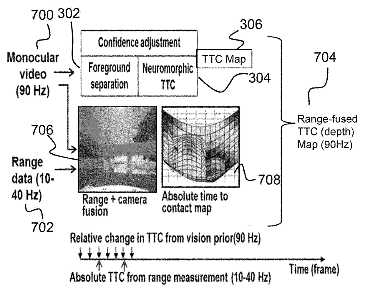
[0031]The present invention relates to a system for detecting obstacles reliably with their ranges by a combination of two-dimensional and three-dimensional sensing and, more specifically, to such a system used to generate an accurate time-to-contact map for purposes of autonomous navigation. The following description is presented to enable one of ordinary skill in the art to make and use the invention and to incorporate it in the context of particular applications. Various modifications, as well as a variety of uses in different applications will be readily apparent to those skilled in the art, and the general principles defined herein may be applied to a wide range of aspects. Thus, the present invention is not intended to be limited to the aspects presented, but is to be accorded the widest scope consistent with the principles and novel features disclosed herein.

[0032]In the following detailed description, numerous specific details are set forth in order to provide a more thoroug...


PUM


Abstract

Described is a robotic system for detecting obstacles reliably with their ranges by a combination of two-dimensional and three-dimensional sensing. In operation, the system receives an image from a monocular video and range depth data from a range sensor of a scene proximate a mobile platform. The image is segmented into multiple object regions of interest and time-to-contact (TTC) value are calculated by estimating motion field and operating on image intensities. A two-dimensional (2D) TTC map is then generated by estimating average TTC values over the multiple object regions of interest. A three-dimensional TTC map is then generated by fusing the range depth data with image. Finally, a range-fused TTC map is generated by averaging the 2D TTC map and the 3D TTC map.

Description

CROSS-REFERENCE TO RELATED APPLICATIONS[0001]The present application is a Continuation-in-Part application of U.S. Ser. No. 15 / 271,025, filed on Sep. 20, 2016, which is a non-provisional application of U.S. Provisional Application No. 62 / 221,523, filed on Sep. 21, 2015, both of which are hereby incorporated herein by reference.[0002]The present application is ALSO a Continuation-in-Part application of U.S. Ser. No. 14 / 795,884, filed Jul. 9, 2015, which is a Continuation-in-Part application of U.S. Ser. No. 14 / 680,057 filed Apr. 6, 2015, both of which are hereby incorporated herein by reference.[0003]The present application is ALSO a non-provisional patent application of U.S. Provisional Application No. 62 / 293,649, filed on Feb. 10, 2016, the entirety of which is hereby incorporated herein by reference.STATEMENT REGARDING FEDERAL SPONSORED RESEARCH OR DEVELOPMENT[0004]This invention was made with Government support under Contract No. HR0011-09-C-000 awarded by DARPA. The government h...

Claims


Application Information

Patent Timeline
Patent Type & Authority Applications(United States)
IPC IPC(8): G01C21/20G06K9/00G05D1/00G01C23/00G06T7/70G06N3/08G06T7/11
CPCG01C21/20G06T7/11G06T7/70G06N3/08G01C23/00G05D1/0055G06K9/00201G06T2200/04G06T2207/10016G06T2207/10028G06T2207/20221G06T2207/30236G06T2207/30261G06T7/73G06T7/579G05D1/024G05D1/0246G06N3/049G06N3/063G06V20/647G06V20/58G06N3/045
Inventor MONTERROZA, FREDYKIM, KYUNGNAMKHOSLA, DEEPAK
Owner HRL LAB
Why Eureka
Try Eureka