Left Atrial Appendage Occluder

a technology of left atrial appendage and occluder, which is applied in the field of medical devices, to achieve the effect of enhancing the occlusion effect and reducing the risk of abrasion or damage to the opening of the left atrial appendage caused by the sealing par

Active Publication Date: 2017-11-16
LIFETECH SCIENTIFIC (SHENZHEN) CO LTD
View PDF3 Cites 7 Cited by
  • Summary
  • Abstract
  • Description
  • Claims
  • Application Information

AI Technical Summary

Benefits of technology

[0024]In the left atrial appendage occluder according to an embodiments of the present disclosure, the radial or axial deformation capacity of the sealing part is set to be greater than the corresponding radial or axial deformation capacity of the fixing part, thereby preventing the situation that the sealing part cannot be optimally fitted with the opening of the left atrial appendage after the fixing part is placed in the left atrial appendage, which in turn enhances the occlusion effect. Meanwhile, owing to the great deformation capacity of the sealing part, risks of abrasion or damage to the opening of the left atrial appendage caused by the sealing part may be reduced.

Problems solved by technology

This pulling may cause the sealing part to not fully fit the opening of the left atrial appendage, thereby forming a blood leakage passage between the left atrium and the left atrial appendage, so that the device is unable to seal the opening optimally and thus allowing the thrombus in the left atrial appendage to flow out therefrom to possibly cause a stroke.

Method used


Image

  • Left Atrial Appendage Occluder
  • Left Atrial Appendage Occluder
  • Left Atrial Appendage Occluder

Examples


first embodiment

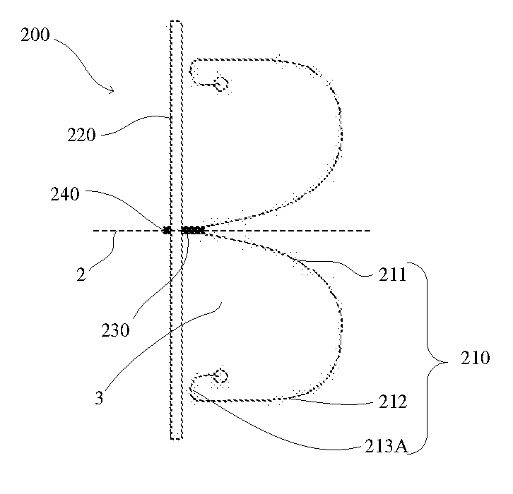
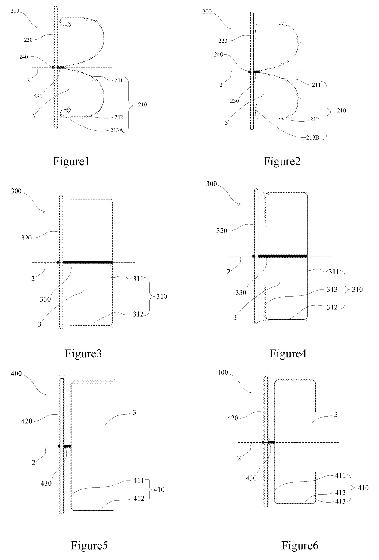
[0073]Referring to FIGS. 1-2, the left atrial appendage occluder 200 according to a first embodiment of the present disclosure has a central axis 2. A fixing part 210 of the left atrial appendage occluder 200 converges at one end and is connected with a connection part 230. Moreover, the fixing part 210 comprises a concave zone 211 formed by radially spreading trolrt this end to a distal end, and a hung zone 212 formed through the extension from the concave zone 211 to a proximal end after bending, wherein the hung zone 212 defines an opening 3 towards the proximal end. The fixing part 210 may be braided integrally with braid wires. For example, the concave zone 211 and the hung zone 212 are braided bodies having a plurality of grids; and the fixing part 210 may also be formed by the cutting of metal tubes. For example, the concave zone 211 and the hung zone 212 respectively comprise a plurality of cut metal rod parts that may be connected with or spaced apart from one another. Acco...

second embodiment

[0076]Referring to FIGS. 3-4, a difference between the left atrial appendage occluder 200 in the first embodiment and a left atrial appendage occluder 300 according to a second embodiment is that the distance between a distal end of a sealing part 320 of the left atrial appendage occluder 300 and a distal end of the fixing part 310 along the direction of a central axis 2 is basically equal to the length of a connection part 330 itself along the central axis 2. The connection part 330 may comprise a rod part and may comprise a braided body, and may further comprise a plurality of metal wires bound together, which will not be described in greater detail herein.

[0077]The fixing part 310 converges at an end portion and is connected with one end of the connection part 330, and the fixing part 310 comprises a distal end surface zone 311 formed by radially spreading from the end portion, and a hung zone 312 formed by extension from the distal end surface zone 311 to the proximal end after ...

third embodiment

[0079]A difference between the left atrial appendage occluder 200 of the first embodiment and a left atrial appendage occluder 400 according to a third embodiment is that a fixing part 410 of the left atrial appendage occluder 400 converges at an end portion and is connected with a connection part 430, and the fixing part 410 comprises a proximal end surface zone 411 formed by radially spreading from this end portion, and a hung zone 412 formed by the extension from the proximal end surface zone 411 to the distal end after bending, wherein an opening 3 is defined by the hung zone 412 towards the distal end. The fixing part 410 may be integrally braided with braid wires. For example, the proximal end surface zone 411 and the hung zone 412 are braided bodies having a plurality of grids. The fixing part 410 may also be formed by cutting a metal tube. For example, the proximal end surface zone 411 and the hung zone 412 respectively comprise a plurality of cut metal rod parts connected w...


PUM


Abstract

A left atrial appendage occluder (200) comprises a sealing part (220), a fixing part (210) disposed at one side of the sealing part (220), and a connection part (230) for connecting the sealing part (220) and the fixing part (210). The radial deformation capacity of the sealing part (220) is greater than the radial deformation capacity of the fixing part (210), and/or, the axial deformation capacity of the sealing part (220) is greater than the axial deformation capacity of the fixing part (210). In the left atrial appendage occluder (200), the radial or axial deformation capacity of the sealing part (220) is configured to be greater than the radial or axial deformation capacity of the fixing part (210), thereby avoiding the situation in which the sealing part (220) is not optimally fitted with the opening of the left atrial appendage (10) when the fixing part (210) is placed inside of the left atrial appendage (10), which in turn enhances the occlusion effect. Additionally, the sealing part (220) has great deformation capacity which reduces the risks of the sealing part (220) causing abrasion to the opening of the left atrial appendage, or even damaging the opening of the left atrial appendage. The fixing part (210) not only avoids the risks but also fixes the occluder in the left atrial appendage (10) more effectively, and prevents the occluder (200) from being disengaged from the left atrial appendage.

Description

TECHNICAL FIELD[0001]The present disclosure relates to a medical device, and particularly relates to a left atrial appendage occluder.BACKGROUND[0002]At present, an occluder can be placed into the left atrial appendage by a catheter-based interventional method to prevent thrombus of the left atrial appendage due to atrial fibrillation from ascending into the brain and then causing a stroke; or to avoid systemic embolism caused by the thrombus reaching other parts of the body through the blood circulation system of a human body. Such left atrial appendage occluders may generally include integrated type and split type in structure. For example, a split occluder usually comprises a fixing part and a sealing part which are connected to each other, wherein the fixing part is placed in the cavity of a left atrial appendage to fix the whole occluder, and the sealing part seals the opening of a left atrial appendage to block the blood from flowing into the cavity of the left atrial appendag...

Claims


Application Information

Patent Timeline
Patent Type & Authority Applications(United States)
IPC IPC(8): A61B17/12A61B17/00
CPCA61B17/12122A61B17/12168A61B17/0057A61B2017/00597A61B2017/00632A61B17/12177A61B17/12172A61B2017/00725A61B2017/0088A61B17/00
Inventor LI, ANNINGCHEN, ZHUO
Owner LIFETECH SCIENTIFIC (SHENZHEN) CO LTD
Why Eureka
Try Eureka