Systems for Printing Three-Dimensional Objects

a three-dimensional object and printing system technology, applied in the field of additive manufacturing techniques, can solve the problems of high cost of metal powder production, difficult processing, and inability to meet the requirements of manufacturing, and achieve the effects of reducing the number of, fast fabrication, and easy handling

Active Publication Date: 2017-11-30
RELATIVITY SPACE INC
View PDF5 Cites 5 Cited by
  • Summary
  • Abstract
  • Description
  • Claims
  • Application Information

AI Technical Summary

Benefits of technology

[0009]In accordance with various embodiments of the present invention, metal objects are fabricated layer by layer in a controlled manner utilizing metal wire as feedstock, enabling the manufacture of 3D structures. Embodiments of the invention only utilize as much feedstock as required to form the object being fabricated, eliminating most (if not all) of the waste and / or recovery processes associated with powder-based techniques. The metallic wire feedstock is more easily handled and enables faster fabrication, as it is deployed only at the exact points where the solid structure is being fabricated. The wire is heated upon contact with the fabrication platform or a previous layer of the structure being fabricated via a pulse of electric current, forming a molten droplet (or “particle”) at the point of contact. The molten droplets adhere in place, enabling the layer-by-layer fabrication of the part. Advantageously, only the single melting / deposition step is required, obviating the need for separate sintering steps to bond the metal particles together. In addition, current is typically only applied to the wire upon contact with the fabrication platform or a previous layer of the structure being fabricated, thereby minimizing heating of the wire (and the structure being fabricated) and preventing formation of electrical arcs at the wire tip.

Problems solved by technology

However, the use of metal powder as a raw material can be problematic for several reasons.
Metal powder is expensive to produce, and generally is more expensive than a wire made from the same material for the same volume of material.
Metal powders are difficult and dangerous to handle.
For example, metal powder that is spilled may form dust in the air that is dangerous to inhale, and such dust may even be an explosion risk.
In addition, the amount of powder required for conventional additive manufacturing technologies is many times greater than that required to make the part, as the entire build area must be filled with powder.
This increases the cost of the process and leads to attrition and waste of powder, which may not be readily reused.
Conventional powder-based processes are also very slow because the spreading of concurrent layers of powder typically must be done precisely to the required layer thickness and must be done across the entire build area for each layer.
Lasers have many safety risks, especially at the powers required for fusing metals.
Using lasers as a source of heat causes issues because the particles must be heated top down to add enough heat to fuse them to the previous layer.
Such top-down heating requires much more heat than would be needed if the heat was applied directly to the joining surfaces, which slows down the overall process and causes the excess heat to be dissipated into the powder bed.
Because of this, there is the danger of unwanted sintering particles in the area around that which the laser is heating.
Therefore, the process requires the use of metals and alloys that have poor heat conduction.
The resolution achieved by spraying metal is generally poor compared to other processes, to the extent that hybrid machines have been developed to deposit metal, allow it to cool, and then use a milling tool to machine it to size.
The speed of the process is slow because sufficient time must be allowed to cool the underlying layer before it can be built upon, as the heat generated by the plasma or electric arc are very high.

Method used


Image

  • Systems for Printing Three-Dimensional Objects
  • Systems for Printing Three-Dimensional Objects
  • Systems for Printing Three-Dimensional Objects

Examples


Embodiment Construction

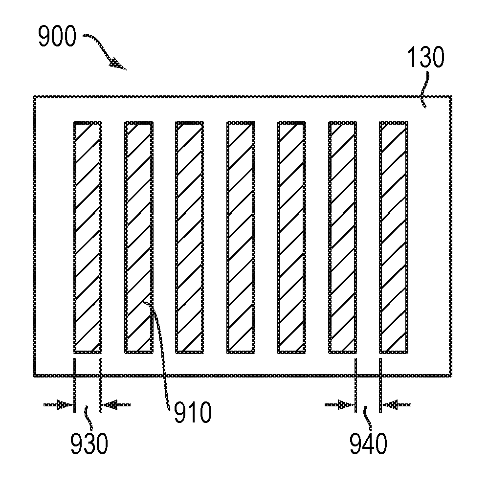
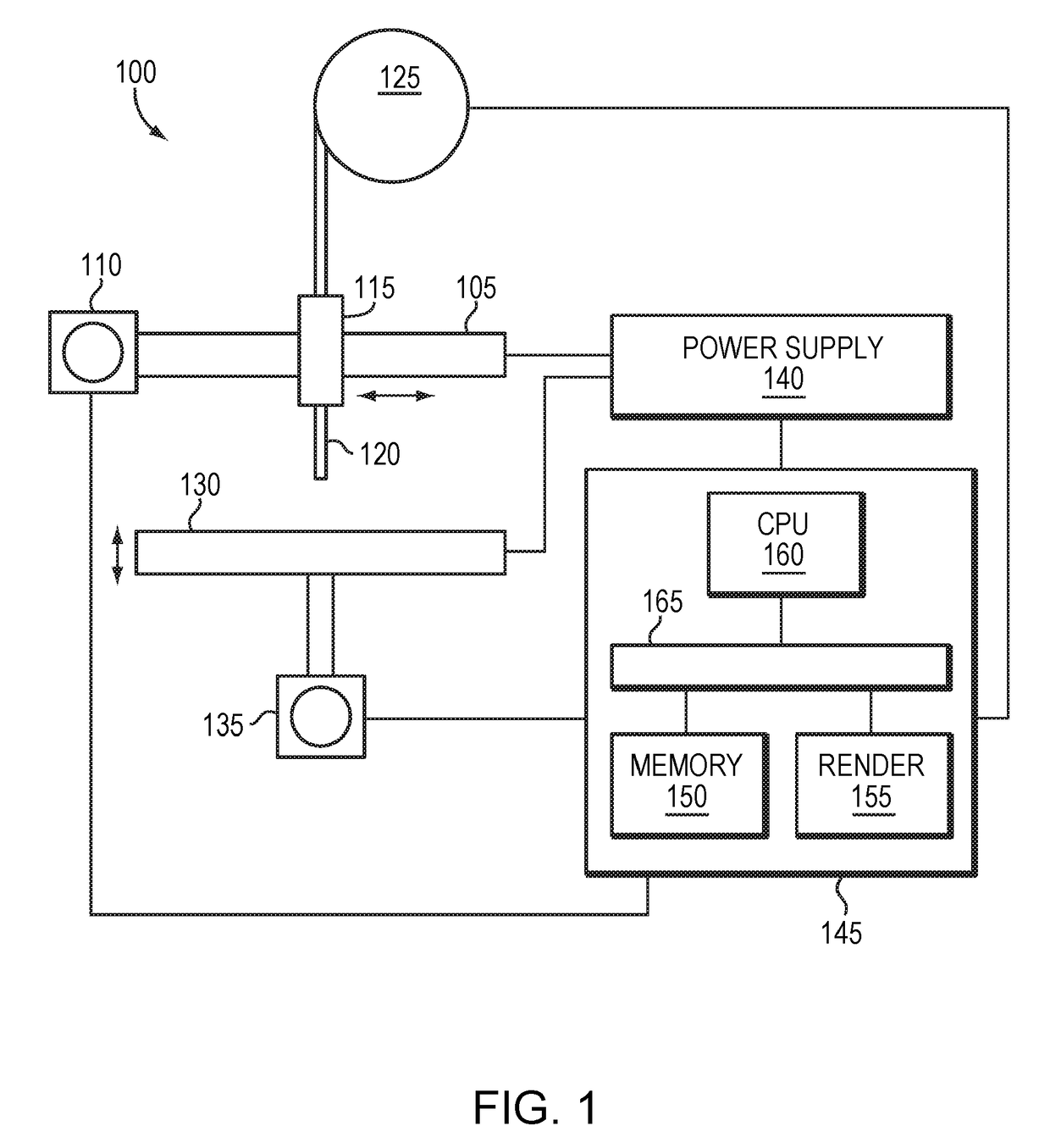
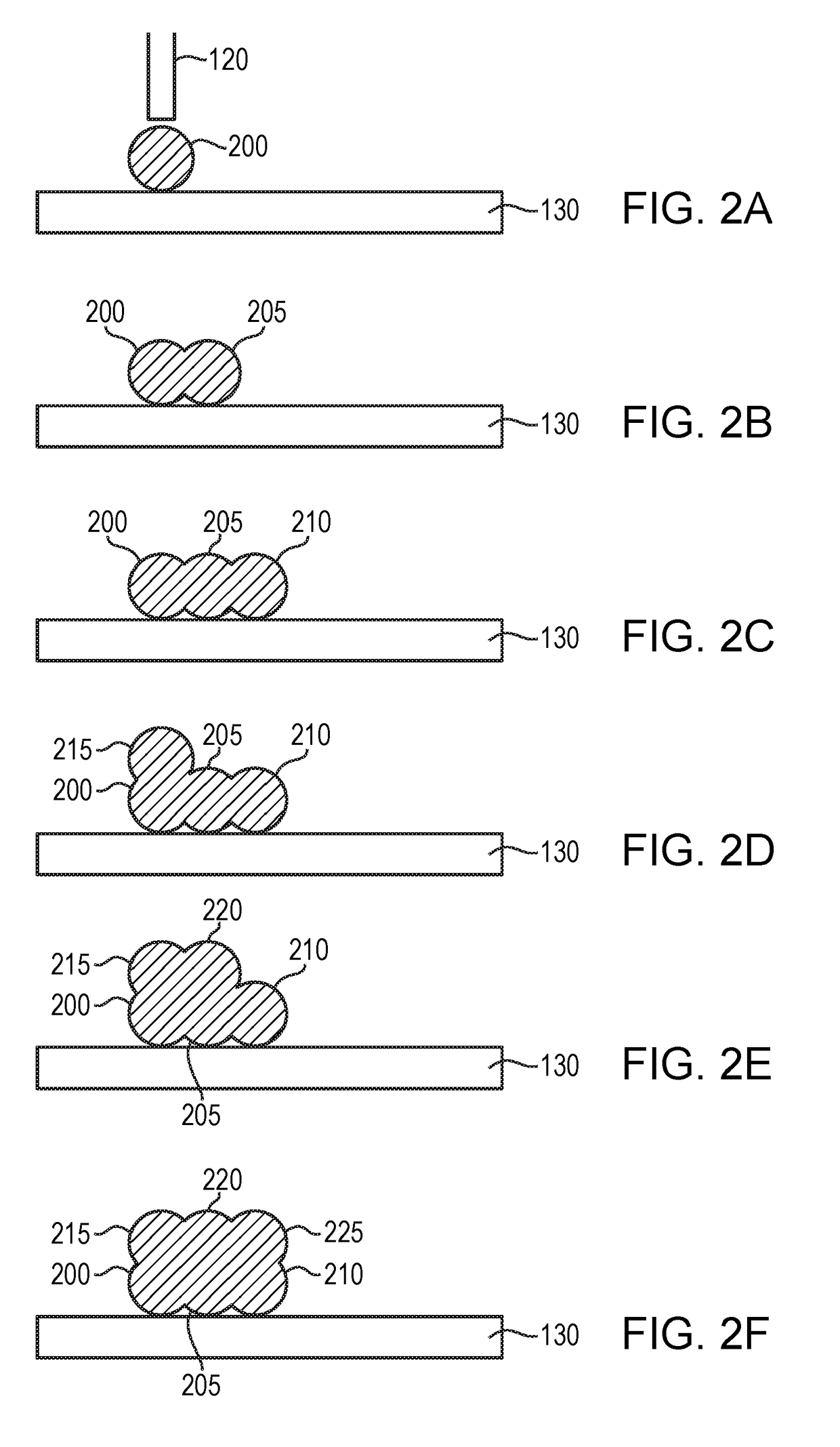
[0034]In accordance with embodiments of the invention, 3D metal structures may be fabricated layer-by-layer using an apparatus 100, as shown in FIG. 1. Apparatus 100 includes a mechanical gantry 105 capable of motion in one or more of five or six axes of control (e.g., one or more of the XYZ planes) via one or more actuators 110 (e.g., motors such as stepper motors). As shown, apparatus 100 also includes a wire feeder 115 that positions a metal wire 120 inside the apparatus, provides an electrical connection to the metal wire 120, and continuously feeds metal wire 120 from a source 125 (e.g., a spool) into the apparatus. A baseplate 130 is also typically positioned inside the apparatus and provides an electrical connection; the vertical motion of the baseplate 130 may be controlled via an actuator 135 (e.g., a motor such as a stepper motor). An electric power supply 140 connects to the metal wire 120 and the baseplate 130, enabling electrical connection therebetween. The motion of t...


PUM

PropertyMeasurementUnit
diameteraaaaaaaaaa
currentaaaaaaaaaa
currentaaaaaaaaaa

Abstract

The present disclosure provides a system for printing at least a portion of a three-dimensional (3D) object. The system may comprise a source of at least one feedstock, a support for supporting at least a portion of the 3D object, a feeder for directing at least one feedstock from the source towards the support, and a power supply for supplying electrical current. The system may comprise a controller operatively coupled to the power supply. The controller may receive a computational representation of the 3D object. The controller may direct the at least one feedstock through a feeder towards the support and may direct electrical current through the at least one feedstock and into the support. The controller may subject such feedstock to Joule heating such that at least a portion of such feedstock may deposit adjacent to the support, thereby printing the 3D object in accordance with the computational representation.

Description

TECHNICAL FIELD[0001]In various embodiments, the present invention relates to additive manufacturing techniques such as three-dimensional (3D) printing, and in particular to the additive manufacturing of metallic objects.BACKGROUND[0002]Additive manufacturing techniques such as 3D printing are rapidly being adopted as useful techniques for a host of different applications, including rapid prototyping and the fabrication of specialty components. To date, most additive manufacturing processes have utilized polymeric materials, which are melted, layer-by-layer, into specified patterns to form 3D objects. The additive manufacturing of metallic objects presented additional challenges, but techniques have been more recently developed to address these challenges.[0003]Existing technologies for the additive manufacture of metal structures may generally be classified in three categories: laser sintering, adhesive bonding followed by sintering, and molten metal deposition. The two sintering t...

Claims


Application Information

Patent Timeline
Patent Type & Authority Applications(United States)
IPC IPC(8): B29C64/386B33Y30/00B29C64/393B33Y50/02B29C64/20
CPCB33Y30/00B33Y50/02B29C64/386B29C64/393B29C64/20B33Y10/00B23K11/0013B23K11/0006B23K11/309Y02P10/25B23K11/257
Inventor BURKE, PAULDOLL, MATEO PENA
Owner RELATIVITY SPACE INC
Why Eureka
Try Eureka