
Tunable Magnonic Crystal Device and Filtering Method

a tunable magnonic crystal and filtering technology, applied in the field of magnonics, can solve the problems of large integrated circuits, saw and baw filters, difficult integration on-chip, etc., and achieve the effects of good filter quality factor (q factor), efficient filtering, and good design scalability

Active Publication Date: 2017-11-30
INTERUNIVERSITAIR MICRO ELECTRONICS CENT (IMEC VZW) +1
View PDF6 Cites 11 Cited by
  • Summary
  • Abstract
  • Description
  • Claims
  • Application Information

AI Technical Summary

Benefits of technology

The patent describes a new filter design that can efficiently filter out signals with high frequencies. The filter also has a good quality factor, meaning it performs well, and is easy to design for different applications.

Problems solved by technology

However, integrated, as well as standalone, devices are relatively large with respect to typical integrated circuits.
SAW and BAW filters are furthermore difficult to integrate on-chip, and difficult to scale without increased losses.
SAW filters are moreover limited in performance and maximum frequency.

Method used


Image

  • Tunable Magnonic Crystal Device and Filtering Method
  • Tunable Magnonic Crystal Device and Filtering Method
  • Tunable Magnonic Crystal Device and Filtering Method

Examples


Embodiment Construction

[0043]The present disclosure will be described with respect to particular embodiments and with reference to certain drawings, but the disclosure is not limited thereto but only by the claims. The drawings described are only schematic and are non-limiting. In the drawings, the size of some of the elements may be exaggerated and not drawn on scale for illustrative purposes. The dimensions and the relative dimensions do not correspond to actual reductions to practice of the disclosure.

[0044]Further, the terms first, second, and the like in the description and in the claims, are used for distinguishing between similar elements and not necessarily for describing a sequence, either temporally, spatially, in ranking, or in any other manner. It is to be understood that the terms so used are interchangeable under appropriate circumstances and that the embodiments of the disclosure described herein are capable of operation in other sequences than described or illustrated herein.

[0045]Moreover...


PUM

PropertyMeasurementUnit
frequenciesaaaaaaaaaa

Abstract

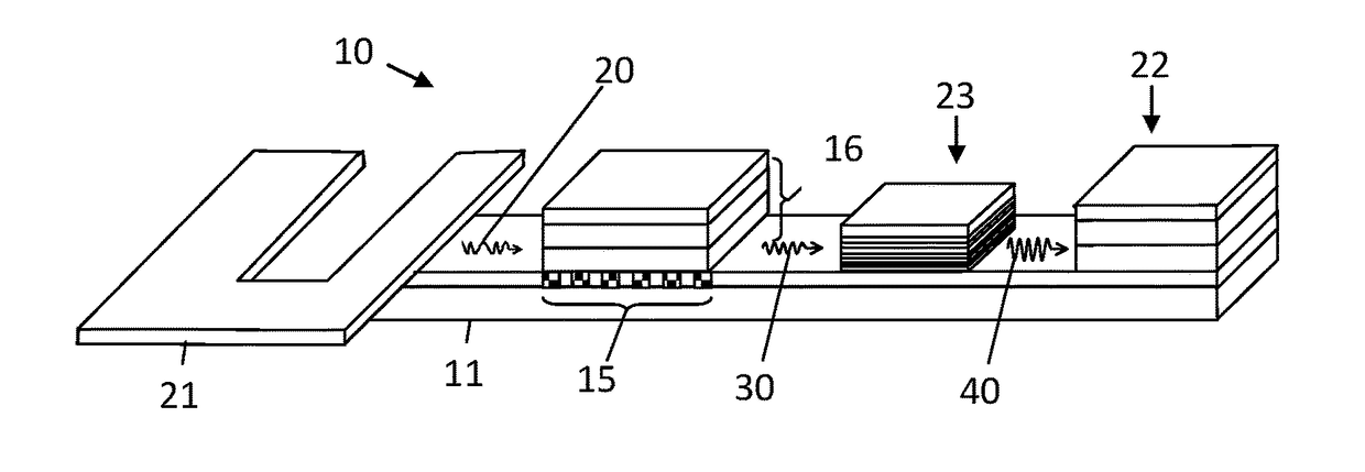
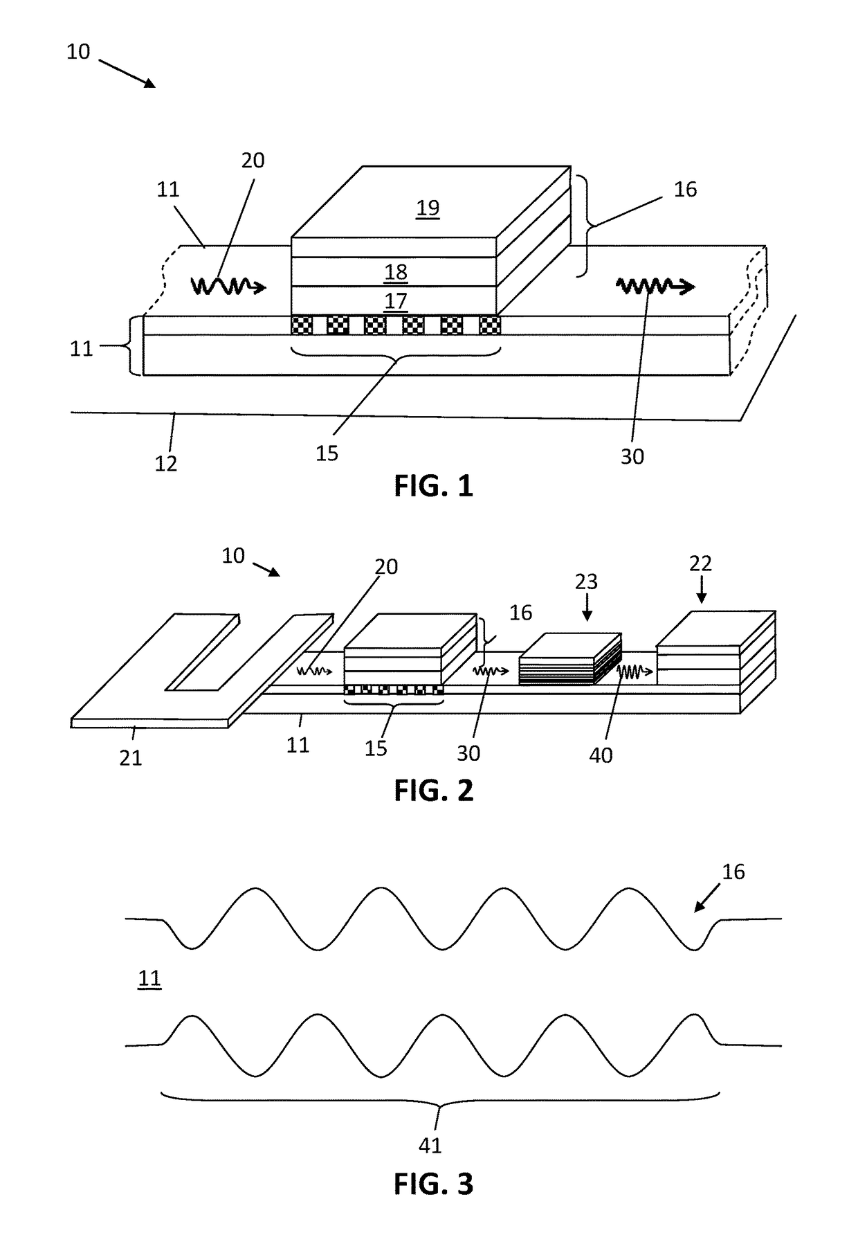
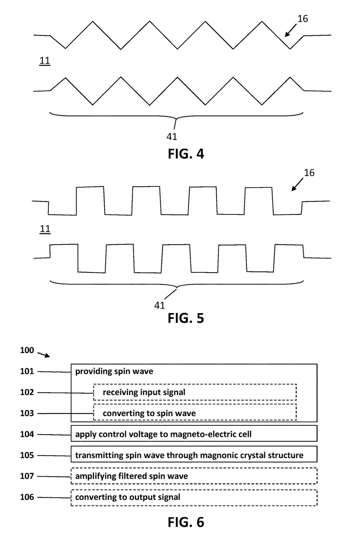
The present disclosure relates to a tunable magnonic crystal device comprising a spin wave waveguide, a magnonic crystal structure in or on the spin wave waveguide, and a magneto-electric cell operably connected to the magnonic crystal structure. The magnonic crystal structure is adapted for selectively filtering a spin wave spectral component of a spin wave propagating through the spin wave waveguide so as to provide a filtered spin wave. The magneto-electric cell comprises an electrode for receiving a control voltage, and adjusting the control voltage controls a spectral parameter of the spectral component of the spin wave via an interaction, dependent on the control voltage, between the magneto-electric cell and a magnetic property of the magnonic crystal structure.

Description

CROSS-REFERENCE TO RELATED APPLICATION[0001]The present application is a non-provisional patent application claiming priority to European Patent Application No. 16171126.2 filed May 24, 2016, the contents of which are hereby incorporated by reference.TECHNICAL FIELD[0002]The disclosure relates to the field of magnonics, e.g., the field of solid state physics in which the properties of spin waves in nano-structure elements are applied. More specifically it relates to a tunable magnonic crystal, systems comprising such a tunable magnonic crystal, and related methods.BACKGROUND[0003]In magnonic devices, wave properties and magnetism are combined on a nano-scale, e.g., spin waves (also referred to as magnons) are formed and applied in such devices. Spin waves may be considered as states of magnetization that propagate as a wave in a suitable material, e.g., a ferromagnetic material shaped and isolated so as to form a magnetic spin wave waveguide element.[0004]A magnonic crystal, as know...

Claims


Application Information

Patent Timeline
Patent Type & Authority Applications(United States)
IPC IPC(8): H01P1/218H01L43/10H01F10/32B82Y10/00B82Y25/00
CPCH01P1/218H01F10/32B82Y10/00B82Y25/00H01L43/10H01P1/215H10N50/20H10N50/85
Inventor CIUBOTARU, FLORINADELMANN, HANNS CHRISTOPHSUN, XIAO
Owner INTERUNIVERSITAIR MICRO ELECTRONICS CENT (IMEC VZW)
Learn More