Method for replacement of phosgene synthesis column catalyst

Active Publication Date: 2017-12-07
WANHUA CHEM GRP
View PDF0 Cites 0 Cited by
  • Summary
  • Abstract
  • Description
  • Claims
  • Application Information

AI Technical Summary

Benefits of technology

The present invention provides a method for quickly replacing the catalyst in a phosgene synthesizing tower, while reducing the phosgene concentration to 0.5 ppm or less. This is achieved through nitrogen purging and ammonia gas purging, which eliminates the need for long periods of nitrogen gas purging and reduces the risk of phosgene leakage. The phosgene concentration can be controlled to be in a range of 0.1 to 0.45%. This method simplifies the process flow, reduces nitrogen gas consumption, and improves process safety.

Problems solved by technology

Activated carbon has a relatively large saturate adsorption rate on phosgene, and it takes a long time to purge so as to completely desorb the phosgene from the activated carbon, which prolongs the time for replacing the catalyst in the phosgene synthesizing tower, and it is also necessary to consume a lot of nitrogen gas.
Described by the patent is that carbon dioxide gas is introduced into a synthesis system after the synthesis system is decompressed, the carbon dioxide gas is used to replace the gas in the system, which however, is less effective in desorbing a small amount of phosgene from the activated carbon, resulting in longer purging time finally.
However, the activated carbon in the phosgene synthesizing tower has a relatively large adsorption rate on the phosgene, and the outlet of the synthesizing tower requires an extremely low concentration of phosgene.
It is difficult to completely remove the phosgene from the phosgene synthesizing tower directly through the vacuum system in a comparatively short time.
However, the phosgene synthesizing tower is a gas-solid reaction system, and the activated carbon cannot be regenerated after reaching its service life.
The method of replacing the catalyst in the synthesizing tower described by the above patent has disadvantages of long phosgene purging time and complicated device for catalyst replacement.
In the prior art, only nitrogen gas is used to directly purge the phosgene synthesizing tower, and it is necessary to consume a large amount of nitrogen gas when phosgene concentration is low in the later stage of purging, and the purging rate is very slow.
Some of the phosgene remains in the synthesizing tower, and there are still great risks in replacing the catalyst in the synthesizing tower.

Method used


Image

  • Method for replacement of phosgene synthesis column catalyst
  • Method for replacement of phosgene synthesis column catalyst

Examples


example 1

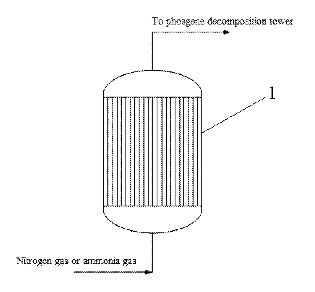
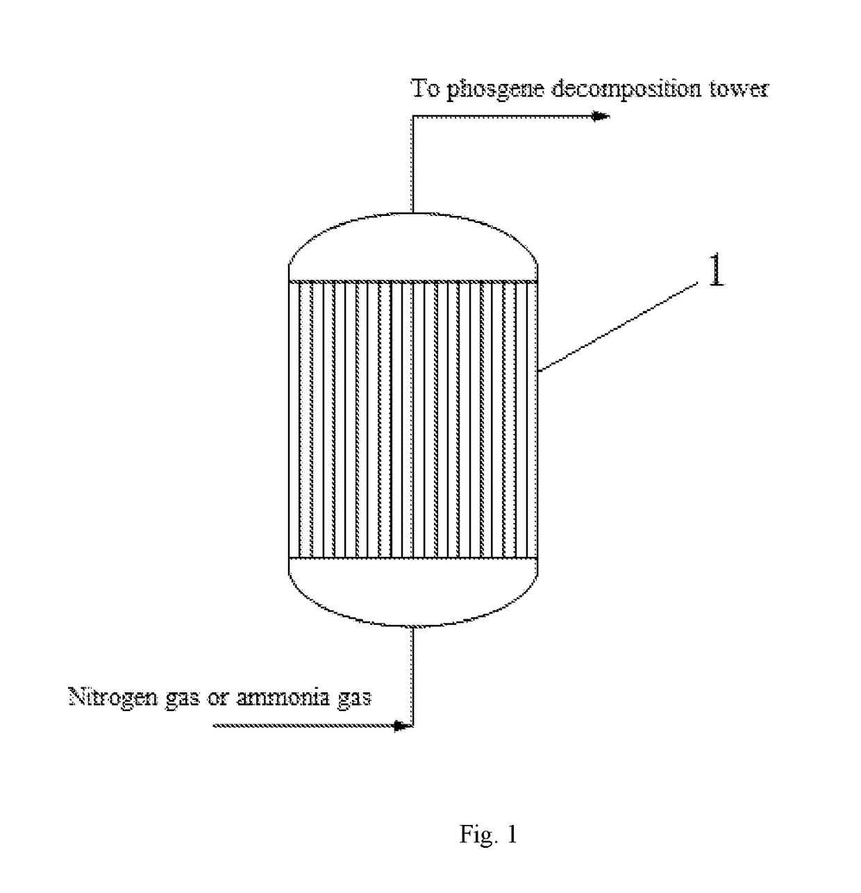
[0040]After feeding to the phosgene synthesizing tower was stopped, 100 Nm3 / h of nitrogen gas was introduced from the bottom of the synthesizing tower, wherein the temperature of the nitrogen gas was 100° C., the moisture content in the nitrogen gas was 100 ppm, and the pressure of the nitrogen gas was 0.15 MPa. The nitrogen gas was continuously introduced for 2 days, and the phosgene concentration at the outlet of the phosgene synthesizing tower was measured as 0.45% (v / v) after purging. Ammonia gas was then introduced for purging. The ammonia gas was first introduced to build up the pressure, the phosgene synthesizing tower was built up pressure to 1 MPa and maintained at this pressure for 2 h, and then the outlet of the phosgene synthesizing tower was opened, and the process of building up pressure was repeated for 8 times as such. And then ammonia gas was continuously introduced, the flow of the ammonia gas was 80 Nm3 / h, the temperature of the ammonia gas was 40° C., and the moi...

example 2

[0041]After feeding to the phosgene synthesizing tower was stopped, 200 Nm3 / h of nitrogen gas was introduced from the bottom of the synthesizing tower, wherein the temperature of the nitrogen gas was 120° C., the moisture content in the nitrogen gas was 300 ppm, and the pressure of the nitrogen gas was 0.2 MPa. The nitrogen gas was continuously introduced for 3 days, and the phosgene concentration at the outlet of the phosgene synthesizing tower was measured as 0.3% (v / v) after purging. Ammonia gas was first introduced to build up the pressure, the phosgene synthesizing tower was built up pressure to 2 MPa and maintained at this pressure for 4 h, and then the outlet of the phosgene synthesizing tower was opened, and the process of building up pressure was repeated for 4 times as such. And then ammonia gas was continuously introduced, the flow of ammonia gas was 100 Nm3 / h, and the temperature of the ammonia gas was 60° C. Purging with the ammonia gas was continued for 3 days, and the...

example 3

[0042]After feeding to the phosgene synthesizing tower was stopped, 400 Nm3 / h of nitrogen gas was introduced from the bottom of the synthesizing tower, wherein the temperature of the nitrogen gas was 150° C., the moisture content in the nitrogen gas was 200 ppm, and the pressure of the nitrogen gas was 0.25 MPa. The nitrogen gas was continuously introduced for 6 days, and the phosgene concentration at the outlet of the phosgene synthesizing tower was measured as 0.1% (v / v) after purging. And then Ammonia gas was introduced for purging, the ammonia gas was first introduced to build up the pressure, the phosgene synthesizing tower was built up pressure to 3 MPa and maintained at this pressure for 5 h, and then the outlet of the phosgene synthesizing tower was opened, and the process of building up pressure was repeated for 5 times as such. And then ammonia gas was continuously introduced for purging, the flow of the ammonia gas is 150 Nm3 / h, and the temperature of the ammonia gas was ...


PUM

PropertyMeasurementUnit
Temperatureaaaaaaaaaa

Abstract

The present invention discloses a method of quickly desorbing phosgene from a catalyst in a phosgene synthesizing tower when the catalyst in the phosgene synthesizing tower is replaced. The method is carried out by first purging out easily-desorbed phosgene from the catalyst activated carbon in the phosgene synthesizing tower with nitrogen gas, then purging with ammonia gas, and the ammonia gas is reacted with the hardly-desorbed phosgene in the catalyst of the phosgene synthesizing tower. Then the phosgene synthesizing tower is rinsed with a water gun and then dried with hot gas. The phosgene content at an outlet of the phosgene synthesizing tower after purging is below 0.5 ppm, which can significantly save the time of the phosgene synthesizing tower for purging the phosgene, greatly reduce the amount of nitrogen gas consumed, and improve the safety of the process operation.

Description

FIELD OF THE INVENTION[0001]The present invention relates to a method of replacing a catalyst in a phosgene synthesizing tower, in particular to a method of quickly desorbing phosgene from a catalyst for phosgene synthesis when the catalyst in the phosgene synthesizing tower is replaced.BACKGROUND OF THE INVENTION[0002]Phosgene is an important organic intermediate which is widely used in pesticides, pharmaceuticals, engineering plastics, polyurethane materials and military. Phosgene can be prepared with various methods. A primary method for industrial production of phosgene at present uses carbon monoxide and chlorine as raw materials, with activated carbon as a catalyst for the synthesis of phosgene wherein the commonly used activated carbon is cocoanut charcoal and coal-based charcoal. 80% of phosgene from industrial production is currently used for the production of isocyanates, mainly used for the production of MDI (diphenylmethane diisocyanate), TDI (toluene diisocyanate) and p...

Claims


Application Information

Patent Timeline
IPC IPC(8): B01J8/06C01B32/80B01J8/00B01J27/20
CPCB01J8/06B01J27/20B01J2208/06C01B32/80B01J8/008B01J8/0278B01J8/0292C07C273/02
Inventor ZHANG, HONGKEYAO, YUZHAO, DONGKECAO, GUANYILIU, XIAOGAOCAO, YOUNIANLI, CHONGMA, YABO
Owner WANHUA CHEM GRP
Why Eureka
Try Eureka