Device for monitoring gas emissions and determining concentration of target gas

Pending Publication Date: 2021-08-12
1829340 ALBERTA LTD
View PDF3 Cites 0 Cited by
  • Summary
  • Abstract
  • Description
  • Claims
  • Application Information

AI Technical Summary

Benefits of technology

The invention has two main advantages: it compresses the air and gas in the cell, making it easier to measure low concentrations and requiring shorter paths, and it automatically compensates for temperature drift, ensuring accurate measurements.

Problems solved by technology

This type of instrument is relatively inexpensive but does not provide any kind of compensation for instrument drift over time which may occur due to the radiation source and / or the photodetector ageing, or accumulation of dirt and dust in the optical path, for example.
Such sensors can work with good stability with the two channels working on the same wavelength (corresponding to an absorption line of the target gas), but the requirement for a separate, sealed gas reference cell containing an inert gas is a serious limitation in a portable, low cost design.
While the low absorption can be overcome by increasing the optical path length between the light source and the detectors, this is achieved with expensive and complicated optical setups such as cavity ring down spectroscopy or intracavity laser absorption, etc.
Similarly, increasing the optical path length in open path systems has some limitations such as the light source can interact with and be scattered or absorbed by other particles in the other than the desired target gas, such as rain, dust or snow thus resulting in erroneous reporting of concentration of target gas.
Moreover they must hit a retroreflector and stay well aligned, in many field conditions wind and other factors can shift the retroreflector causing increased maintenance requirements.
Other problems with existing sensors include power inefficiency due to the need for continuous temperature stabilization and light source or laser requirements limiting their application in remote location deployment.

Method used


Image

  • Device for monitoring gas emissions and determining concentration of target gas
  • Device for monitoring gas emissions and determining concentration of target gas
  • Device for monitoring gas emissions and determining concentration of target gas

Examples


Embodiment Construction

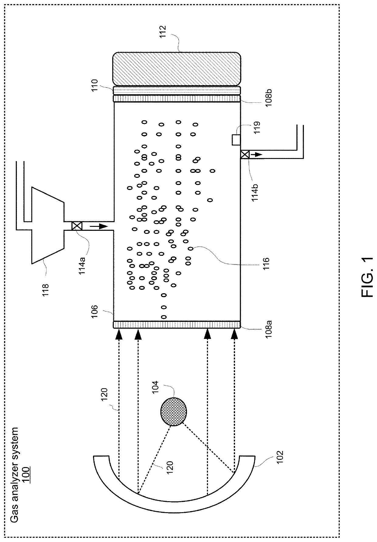
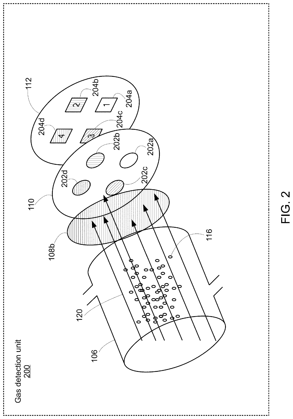
[0026]FIG. 1 shows a gas analyzer system 100 according to an exemplary embodiment. The gas analyzer system 100 comprises a parabolic reflector 102, a radiation source 104, a gas cell 106, a first germanium window 108a placed upstream of the gas cell 106, a second germanium window 108b that is located downstream of the gas cell, a filter array 110 sandwiched between the second germanium window 108b and a detector-read-out assembly 112. The gas cell further comprises an inlet check valve 114a and an outlet back pressure valve 114b via which gas molecules 116 of a target gas enter and exit the gas cell 106, respectively. The inflow and outflow of gas molecules 116 into and out of the gas cell 106 is controlled by a compressor 118 located prior the inlet valve. A pressure sensor 119 is mounted within the gas cell 106 for measuring the pressure within the cell 106.

[0027]In this embodiment, the gas analyzer system 100 is used to measure the concentration of the target gas. The gas analyze...


PUM


Abstract

An emission monitoring device is for measuring concentration of a target gas. The emission monitoring system comprises a gas cell, a radiation source, a detector, a readout circuit, and a controller. In response to a first event, the controller causes the radiation source to enter a first operational mode and the readout circuit to sample and hold a first output signal while the radiation source is operating in the first operational mode. In response to a second event, the controller causes the radiation source to enter into a second operational mode and the readout circuit to obtain a difference between the first output signal and a second output signal, the second output signal of being detected while the radiation source is operating in the second operational mode, wherein the controller converts the difference into an output value representing the concentration of the target gas.

Description

CROSS-REFERENCE TO RELATED APPLICATIONS[0001]This application claims the benefit of priority of U.S. Provisional Application No. 62 / 971,395 filed Feb. 7, 2020, which is incorporated herein by reference.BACKGROUND OF THE INVENTION(1) Field of the Invention[0002]The invention pertains generally to sensors for detecting gas emissions. More specifically, the invention relates to an emission monitoring system for measuring the concentration of a target gas using a radiation source that emits infrared (IR) light.(2) Description of the Related Art[0003]Optical absorption techniques such as non-dispersive infrared (NDIR) measurement have been recognized for many years as sensitive, stable and reliable methods of gas concentration measurement. In a typical NDIR method, the selective absorption of infrared radiation by certain gas species of interest is measured to determine the concentration of the target gas in a sample. This has a wide variety of applications—for example, NDIR measurements...

Claims


Application Information

Patent Timeline
IPC IPC(8): G01N21/3504G01N21/27
CPCG01N21/3504G01N2021/3536G01N21/27G01N21/314
Inventor DATTNER, YONATHAN
Owner 1829340 ALBERTA LTD
Why Eureka
Try Eureka