
Method for manufacturing transparent pattern print steel plate

Active Publication Date: 2017-12-14
POSCO
View PDF21 Cites 7 Cited by
  • Summary
  • Abstract
  • Description
  • Claims
  • Application Information

AI Technical Summary

Benefits of technology

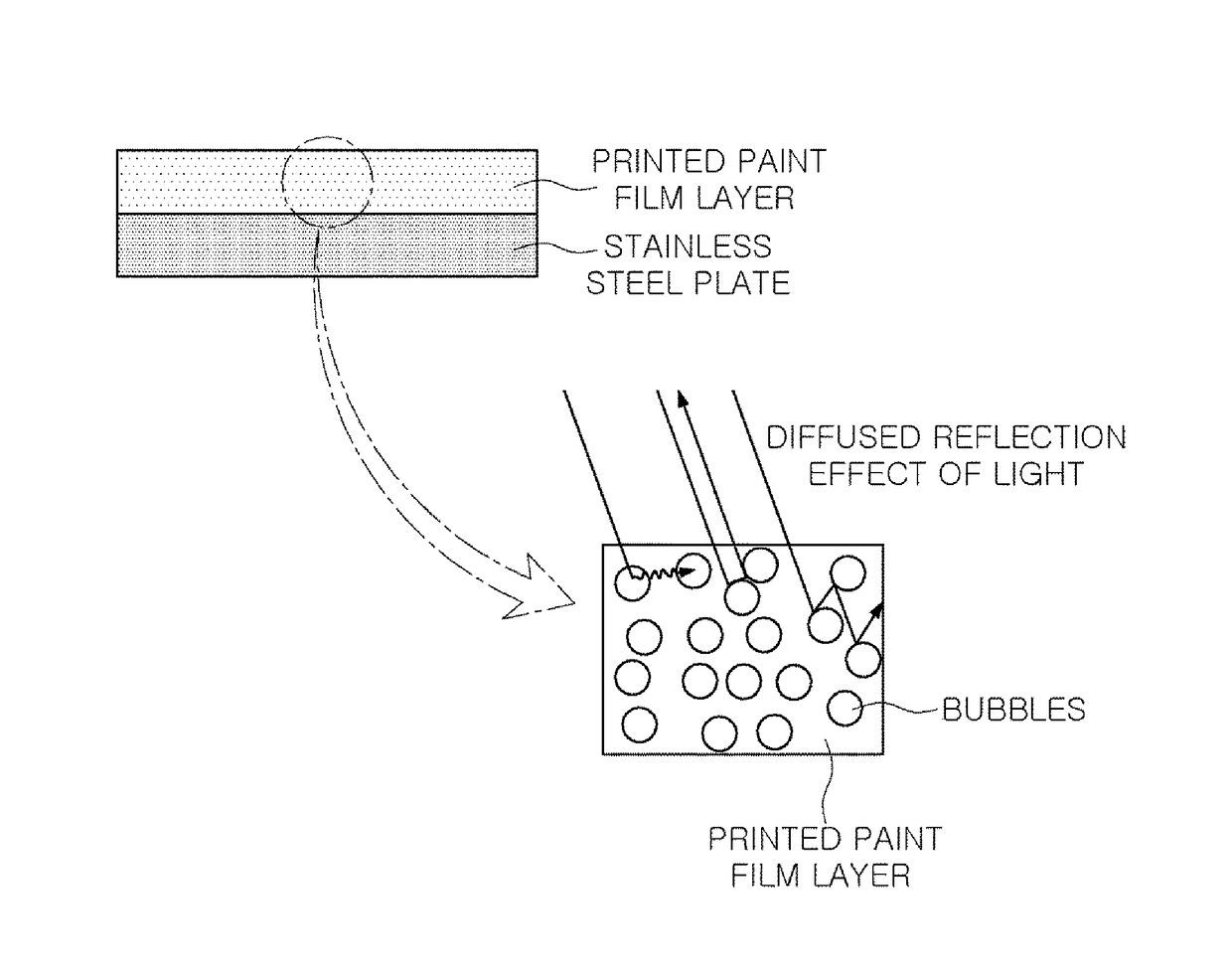
The present invention is about a new method for making a transparent pattern printed steel plate. This method simplifies the process of etching patterns, reducing costs. The resulting plate is much harder and easier to work with.

Problems solved by technology

Since products are produced through sequential operations of polymer pattern printing, drying, acid etching, washing, polymer pattern removal, and washing, the process may be complicated and operating costs may be high.
However, when an excessive amount of silica is added to a solution, the hardness of a paint film may be increased, processability may be poor, and resolution may be lowered.
Further, in a printing process using inkjet printing, a phenomenon in which several micro-silica particles plug an ink jet nozzle may be problematic.

Method used


Image

  • Method for manufacturing transparent pattern print steel plate
  • Method for manufacturing transparent pattern print steel plate

Examples


embodiment

[0061]1. Printed Paint Film Layer Formed on Stainless Steel Plate

[0062]A stainless steel plate having a thickness of 0.4 mm to 0.5 mm was irradiated with plasma having a strength of 800 W in air for 10 seconds, and then, a transparent ultraviolet curable ink containing no pigment was pattern printed with inkjet printing. In this case, the ink was jetted at a speed of 12 kHz, and a continuous process was performed to be within 2 seconds from ink jetting to initiation of ultraviolet curing. Table 1 provides the results of degrees of glossiness and printing adhesion according to changes in painted film thicknesses.

TABLE 1Painted FilmDegree ofPrintingClassificationThicknessGlossinessAdhesionEmbodiment 1140 to 45GoodEmbodiment 25 3 to 25GoodEmbodiment 31010 to 35GoodEmbodiment 41515 to 40GoodEmbodiment 52025 to 50GoodComparative3055 to 60DefectiveExample 1

[0063]As shown in Table 1, it was confirmed that, in Embodiments 1 to 5, in which a painted film thickness is 1 μm to 20 μm, adhesion ...


PUM

PropertyMeasurementUnit
Timeaaaaaaaaaa
Timeaaaaaaaaaa
Timeaaaaaaaaaa

Abstract

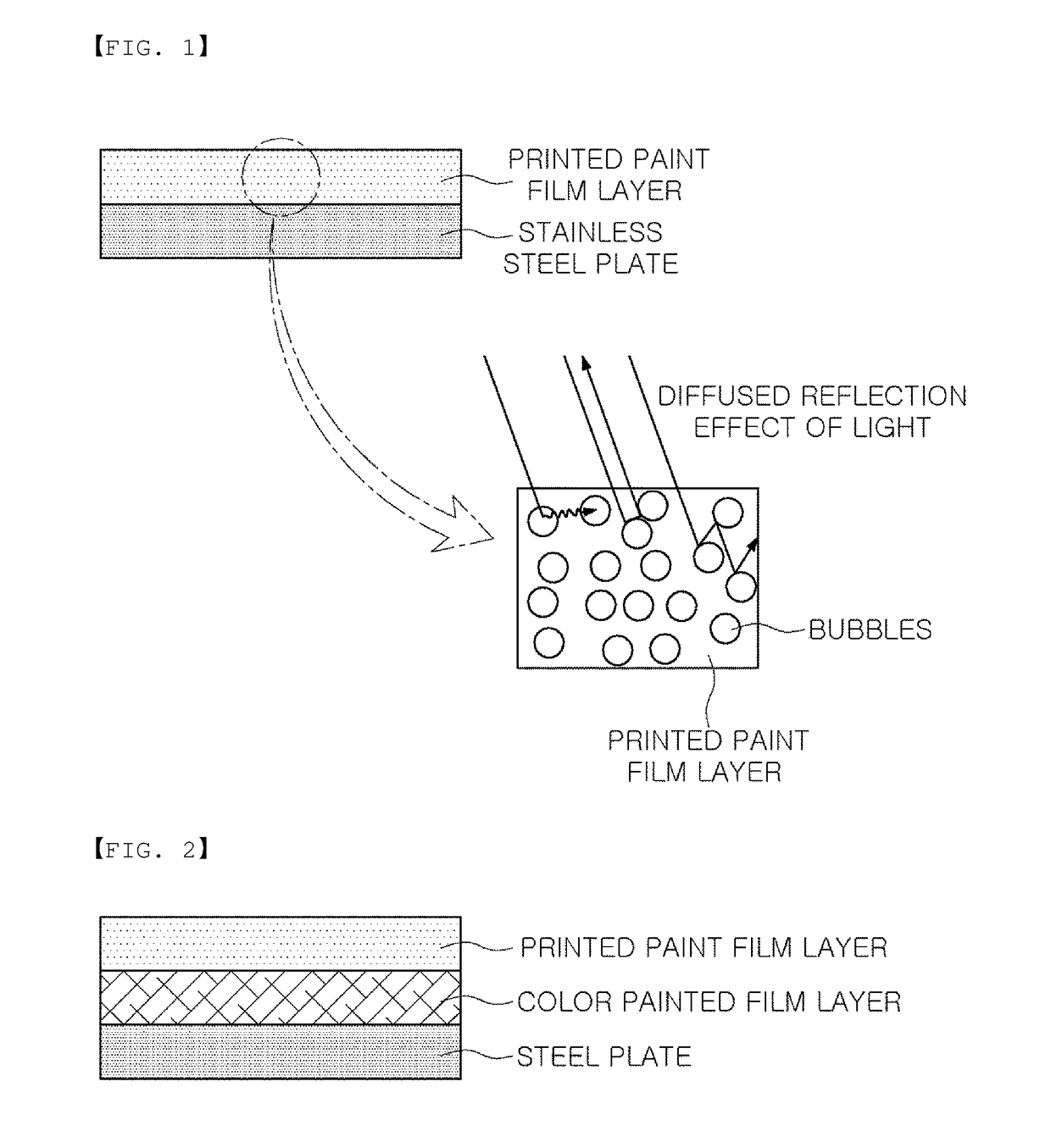
A method of manufacturing a transparent pattern printed steel plate includes forming a printed paint film layer by jetting transparent ink onto at least one surface of a steel plate, and curing the printed paint film layer with ultraviolet light to form a cured printed paint film layer. Further, a method of manufacturing a transparent pattern printed steel plate includes preparing a steel plate having a color painted film layer formed on at least one surface thereof, forming a printed paint film layer by jetting transparent ink onto the color painted film layer, and curing the printed paint film layer to form a cured printed paint film layer.

Description

TECHNICAL FIELD[0001]The present disclosure relates to a method of manufacturing a transparent pattern printed steel plate.BACKGROUND ART[0002]In the case of applying designs to steel plates by acid etching, pattern printing is performed on the steel plates using polymer resins, and then, portions of the steel plates without patterns printed thereon are dissolved in acid through acid etching to produce etching patterns. In addition, after the etching of steel plates, polymer pattern printed portions should be melted to expose the non-etched portions of the steel plates. Since products are produced through sequential operations of polymer pattern printing, drying, acid etching, washing, polymer pattern removal, and washing, the process may be complicated and operating costs may be high.[0003]On the other hand, when a printed steel plate is manufactured by a method of applying a design to a steel plate using a solution, silica particles as a matting agent are added together with the s...

Claims


Application Information

Patent Timeline
IPC IPC(8): B05D3/06B05D7/14B05D3/02
CPCB05D3/061B05D7/14B05D3/02B05D3/067B05D3/142B05D7/53B05D2202/10B41M5/0047B41M5/0058B41M7/0081B05D1/02B05D3/00B05D3/06B05D5/00Y02P20/54
Inventor KIM, JIN-TAEKIM, JONG-SANGHA, BONG-WOOCHOI, YANG-HOLEE, JUNG-HWANCHOI, HA-NAKIM, JONG-KOOK
Owner POSCO
Learn More