Shaper for vertebral fixation rods

a technology for fixing rods and vertebrae, which is applied in the field of rod shape, can solve the problems of compromising the rotation of the rod, severe deformation, and medical staff exposure to additional radiation

Active Publication Date: 2017-12-21
MAZOR ROBOTICS
View PDF5 Cites 166 Cited by
  • Summary
  • Abstract
  • Description
  • Claims
  • Application Information

AI Technical Summary

Benefits of technology

[0020]According to yet another implementation of the above described methods, the rod shaping system may further comprise a rod thinning module, adapted to reduce the cross-sectional area of the rod at predetermined locations, such that the rod has increased flexibility at the predetermined locations. In such an implementation, the rod thinning module should be able to adapt the cross sectional dimension of the rod in different planes according to clinical need. In either of these cases, the rod thinning module may reduce the cross sectional dimension of the rod by means of indentations generated in the rod at the predetermined locations. In that method, the indentations may be generated by appropriately shaped plunger pistons.
[0021]As an alternative to the use of plunger pistons, the rod thinning module may reduce the diameter of the rod by means of mechanical removal of material from the rod at the predetermined locations. That mechanical removal of material may be performed by a controlled milling action.
[0025](iii) using the rod-shaping system to reduce the cross-sectional area of the rod at rod locations corresponding to regions falling between the vertebrae when the rod is attached to the subject, such that the rod has increased flexibility at the regions.

Problems solved by technology

This can be a problematic task since the spine may be severely deformed in a scoliotic patient, and even in a non-scoliotic patient, adjacent vertebrae generally have differing protrusion heights and are not linearly aligned because of the natural spinal lordosis.
However this procedure is prone to inaccuracies and since a typical fusion rod is intended to be a high strength component and is generally made of titanium or stainless steel and is typically 5 mm in diameter, the surgeon often has to exert considerable force using pliers to bend the rod appropriately during connection, in order to ensure that the rod fits without exerting undue pressure on the patient's vertebrae.
However, in order to perform intra-operative bending of the rod to match the desired shape in 3D, this system requires the generation of additional images during the procedure, which subjects the patient and possible also the medical staff, to additional radiation exposure.
Additionally, although such rod assemblies may be used to fuse two adjacent vertebrae, there are often cases of scoliosis and severe deformities where the region of the spine to be treated may include even 10 or more vertebrae.
Such a method may further compromise the rotation of the rod, such that the plurality of plunger pistons can shape the rod in three dimensions.

Method used


Image

  • Shaper for vertebral fixation rods
  • Shaper for vertebral fixation rods
  • Shaper for vertebral fixation rods

Examples


Embodiment Construction

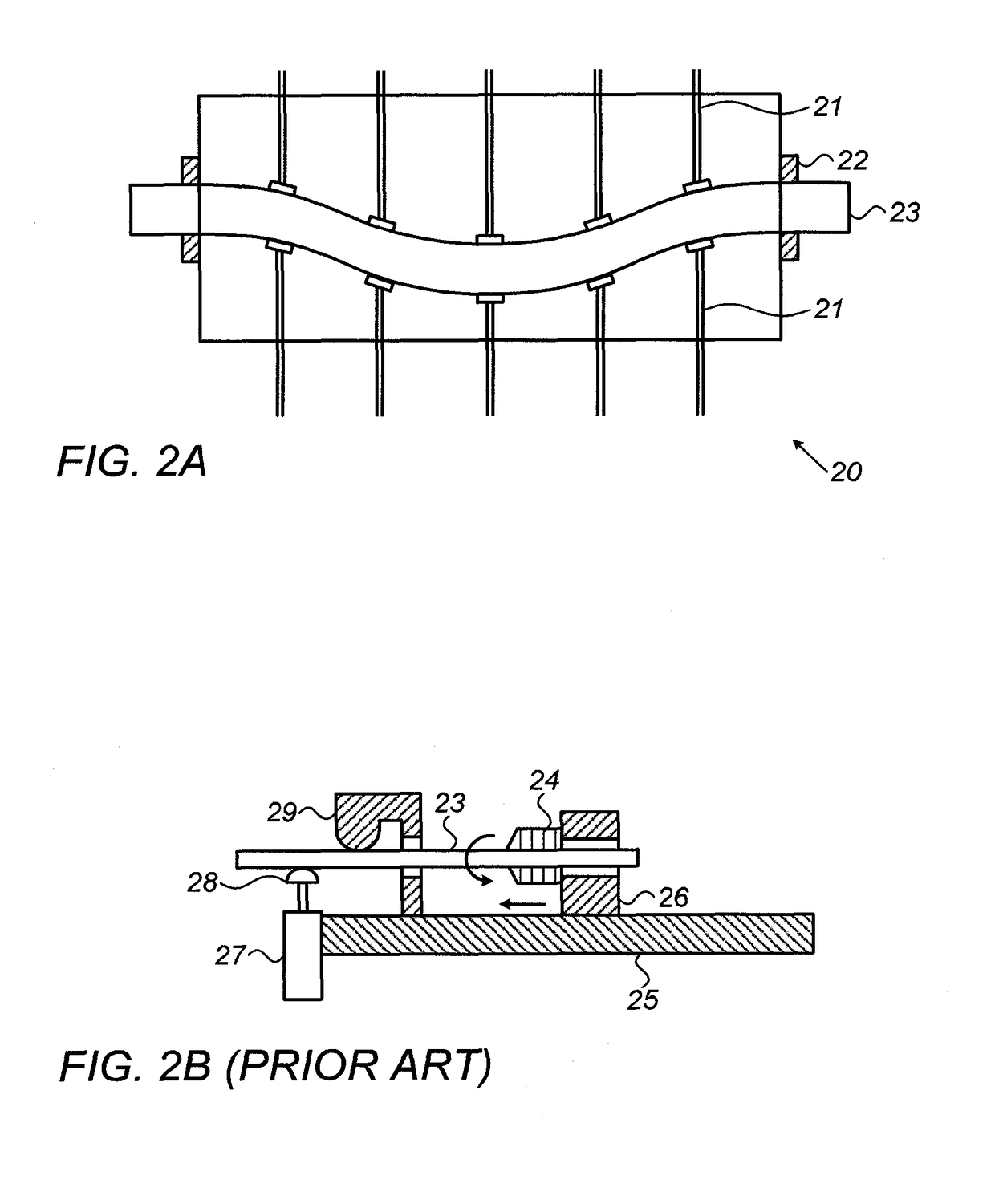
[0037]Reference is now made to FIG. 2A, which illustrates schematically a plan view of a rod shaping apparatus 20, using mechanical plungers or pistons 21 for shaping the rod. The rod 23 is firmly held in end clamps 22, which may be rotatable to enable three-dimensional bent shapes to be executed. The plungers or pistons 21 may be driven by hydraulic or pneumatic cylinders, or by electric motors (none of which are shown in FIG. 2A), or by any other motion impartation device that can provide sufficient force to bend the rod as required. In the exemplary apparatus shown in FIG. 2A, the rod-bending process in the plane shown is performed by sets of plungers or pistons, arranged opposite to each other, such that good control is achieved of the bending process, and the bending can be achieved in either direction of concavity. However, it is to be understood that a bend in any direction can also be achieved by having the plunger or piston oriented only at the intended concave side of the ...


PUM

PropertyMeasurementUnit
diameteraaaaaaaaaa
flexibilityaaaaaaaaaa
dimensionaaaaaaaaaa

Abstract

A system for rod bending for use in robotic spinal surgery, enabling the correct bending of a fusion rod to match the shape required to accurately pass through the heads of the pedicle screws. The system uses data generated by information provided to the robot by the surgeon's preoperative plan, optionally augmented by feedback from the robot control system of deviations encountered intraoperatively. Such deviations could occur, for example, when the surgeon decides intraoperatively on a different trajectory or even to skip screws on one vertebra, in which case, the robot will be commanded to perform the alternative procedure, with commensurate instructions relayed to the control system of the rod-bending machine. The system is also able to thin down the rod at predetermined locations along its length, adapted to be at selected intervertebral locations, for maintaining limited flexibility between vertebrae, instead of fixating them.

Description

FIELD OF THE INVENTION[0001]The present invention relates to the field of the shaping of rods used for the fixation of vertebrae in spinal fusion treatment, and their use in robotically directed surgery, especially shaping performed using information obtained from pre-operatively generated images of the surgical site and intraoperative updates.BACKGROUND OF THE INVENTION[0002]When performing surgery to insert vertebral fixation rods for spinal fusion, there is a need to ensure that the fusion rod is passed accurately between the tulips of the pedicle screws, before the screws are tightened onto the rod. This can be a problematic task since the spine may be severely deformed in a scoliotic patient, and even in a non-scoliotic patient, adjacent vertebrae generally have differing protrusion heights and are not linearly aligned because of the natural spinal lordosis. Reference is made to FIG. 1 which illustrates such a typical vertebral fixation rod implementation, in which the rod 11 h...

Claims


Application Information

Patent Timeline
Patent Type & Authority Applications(United States)
IPC IPC(8): A61B17/88A61B34/10B21D7/12B21D7/14A61B17/00A61B17/70
CPCA61B17/8863A61B34/10B21D7/12A61B2017/00526A61B17/70A61B2034/108B21D7/14A61B17/7002A61B5/0036A61B5/107
Inventor ZUCKER, EDOSHOHAM, MOSHE
Owner MAZOR ROBOTICS
Why Eureka
Try Eureka