Foam cushion respiratory apparatus

a foam cushion and respiratory apparatus technology, applied in the field of foam cushion respiratory apparatus, medical devices or apparatus, can solve the problems of csr harm, cardiovascular disease and brain damage, excessive daytime somnolence, etc., and achieve the effects of improving comfort, cost, efficacy, and ease of us

Active Publication Date: 2017-12-21
RESMED LTD
View PDF4 Cites 12 Cited by
  • Summary
  • Abstract
  • Description
  • Claims
  • Application Information

AI Technical Summary

Benefits of technology

[0042]The present technology is directed towards providing medical devices used in the diagnosis, amelioration, treatment, or

Problems solved by technology

It often causes excessive daytime somnolence, and it may cause cardiovascular disease and brain damage.
It is possible that CSR is harmful because of the repetitive hypoxia.
In some patients CSR is associated with repetitive arousal from sleep, which causes severe sleep disruption, increased sympathetic activity, and increased afterload.
Symptoms include dyspnea, morning headache and excessive daytime sleepiness.
Some NMD patients are characterised by progressive muscular impairment leading to loss of ambulation, being wheelchair-bound, swallowing difficulties, respiratory muscle weakness and, eventually, death from respiratory failure.
Symptoms of respiratory failure in NMD include: increasing generalised weakness, dysphagia, dyspnoea on exertion and at rest, fatigue, sleepiness, morning headache, and difficulties with concentration and mood changes.
Chest wall disorders are a group of thoracic deformities that result in inefficient coupling between the respiratory muscles and the thoracic cage.
Scoliosis and/or kyphoscoliosis may cause severe respiratory failure.
Symptoms of respiratory failure include: dyspnoea on exertion, peripheral oedema, orthopnoea, repeated chest infections, morning headaches, fatigue, poor sleep quality and loss of appetite.
For other forms of therapy, such as the delivery of oxygen, the patient interface may not include a seal sufficient to facilitate delivery to the airways of a supply of gas at a positive pressure of about 10 cm H2O.
The design of a patient interface presents a number of challenges.
As a consequence of these challenge

Method used


Image

  • Foam cushion respiratory apparatus
  • Foam cushion respiratory apparatus
  • Foam cushion respiratory apparatus

Examples


Embodiment Construction

[0140]Before the present technology is described in further detail, it is to be understood that the technology is not limited to the particular examples described herein, which may vary. It is also to be understood that the terminology used in this disclosure is for the purpose of describing only the particular examples discussed herein, and is not intended to be limiting.

5.1 Treatment Systems

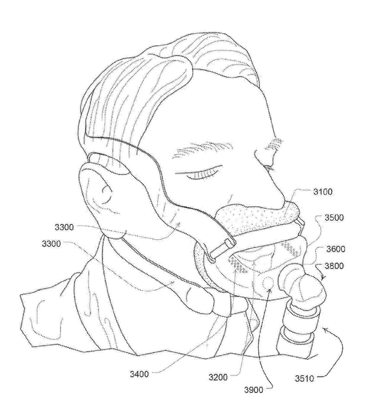
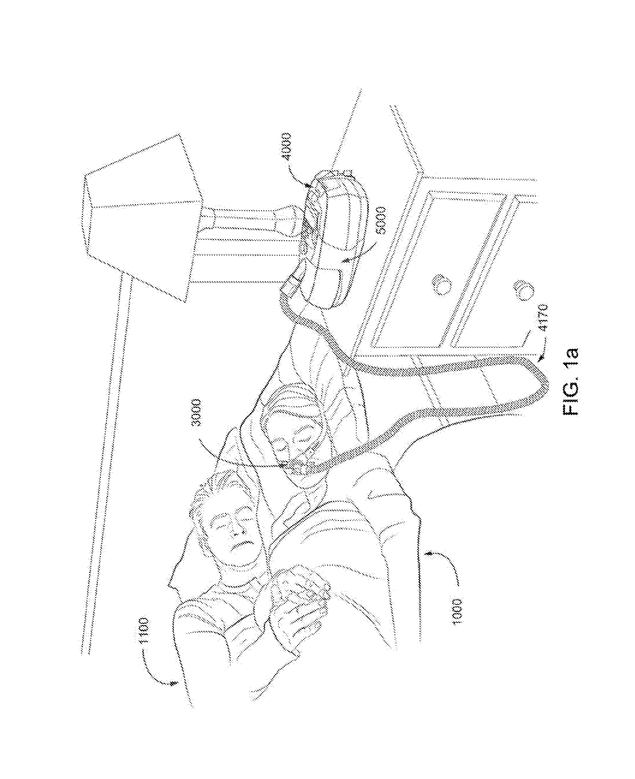
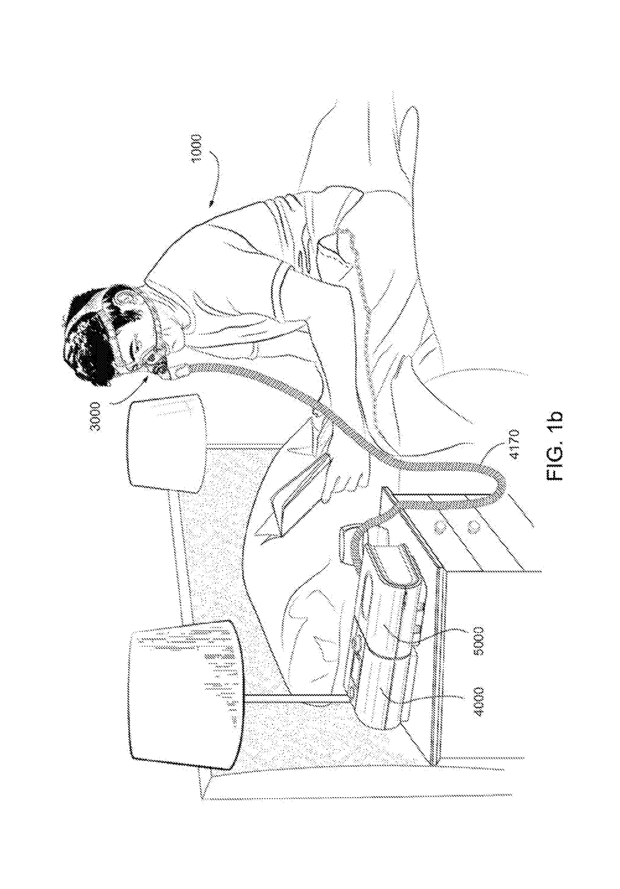
[0141]In one form, the present technology comprises apparatus for treating a respiratory disorder. The apparatus may include a flow generator or blower for supplying pressurised respiratory gas, such as air, to the patient 1000 via an air delivery conduit, such as a tube, leading to a patient interface 3000.

5.2 Therapy

[0142]In one form, the present technology may involve a method for treating a respiratory disorder by applying positive pressure to the entrance of the airways of a patient 1000.

5.2.1 CPAP for OSA

[0143]In one example, the present technology may involve a method of treating Obstruc...


PUM


Abstract

A mask apparatus for a respiratory treatment can permit delivery of breathable gas to a user. In one example, the mask may employ a frame and cushion to form a seal for both mouth and nose. The frame may be adapted for coupling with a respiratory treatment apparatus so as to permit communication of a pressurized gas from the respiratory treatment apparatus. The cushion, which may be foam, and a frame component may be made in an overmoulding process that moulds the frame onto a pre- formed foam cushion. Such a moulding process may form a mechanical and/or chemical bonding of the foam and mask frame component. The mask frame component may be a shell of plenum chamber, such as for both nose and mouth. Various features of the cushion may further promote sealing and comfort for the under the nose design.

Description

1 CROSS REFERENCE TO RELATED APPLICATIONS[0001]This application claims the benefit of the filing dates of U.S. Provisional Patent Application No. 62 / 062,444 filed Oct. 10, 2014, the disclosure of which is hereby incorporated herein by reference.2 BACKGROUND OF THE TECHNOLOGY2.1 Field of the Technology[0002]The present technology relates to one or more of the detection, diagnosis, treatment, prevention and amelioration of respiratory-related disorders. In particular, the present technology relates to medical devices or apparatus, and their use. Such devices may include an interface for directing a treatment to a patient respiratory system.2.2 Description of the Related Art[0003]The respiratory system of the body facilitates gas exchange. The nose and mouth form the entrance to the airways of a patient.[0004]The airways consist of a series of branching tubes, which become narrower, shorter and more numerous as they penetrate deeper into the lung. The prime function of the lung is gas ...

Claims


Application Information

Patent Timeline
IPC IPC(8): A61M16/06A61M16/08A61M16/00A61M16/10
CPCA61M16/0622A61M16/0066A61M16/0633A61M16/0683A61M2207/10A61M16/105A61M2016/0027A61M2016/0039A61M2205/42A61M16/0825A61M16/06A61M16/0616A61M16/107
Inventor MOILER, GRANTQUARMBY, NIGEL
Owner RESMED LTD
Why Eureka
Try Eureka