Rowing machine

a technology of a rotary wheel and a rotor, which is applied in the field of rotors, can solve the problems of easy leakage of oil cylinders, pollution of the environment, and high production costs, and achieve the effects of adjusting the damping strength, simple structure, and good simulation

Inactive Publication Date: 2017-12-21
XIAMEN AOLRO TECH
View PDF5 Cites 5 Cited by
  • Summary
  • Abstract
  • Description
  • Claims
  • Application Information

AI Technical Summary

Benefits of technology

[0003]The present invention is provided with a new rowing machine to overcome the disadvantages of the existing known technology, this new structure application can not only adjust the damping strength to adapt to different intensity of training, but also achieve simulation of single hand / double hands rowing. No resistance exists during the user returns hand / hands back, making the machine with well simulation effect, simple structure and low producing cost.
[0021]Compared with the prior art, the invention has the following beneficial effects:
[0022]The present invention adopts the rotating plate, the oar components, the accelerating transition transmission mechanism and the rotation damping mechanism to form the main components of the new rowing machine, and the rotating plate with a fixing rotating shaft is rotatably assembled to the rack through the rotating shaft; two oar components are respectively connected to the two ends of the rotating shaft by unilateral bearings in universal joining way to unilaterally drive the rotating plate to rotate when swinging; the rotation damping mechanism assembled to the rack; the acceleration type transition transmission mechanism is assembled between the rotating plate and the damping mechanism to drive a damping wheel of the damping mechanism when the rotating plate rotates. This kind of new rowing machine of the present invention can not only adjust the damping strength to adapt to different intensity of training, but also achieve simulation of single hand / double hands rowing. the machine has well simulation effect, simple structure and low producing cost; it is a rowing machine with new structure.
[0023]The oar components of the present invention are linked to the damping mechanism through the rotating plate and the transmission mechanism; in this way, there is no drawback that the webbing of the existing known technology is easily broken. The oar components of the present invention are connected to the rotating shaft through the bearings and unilateral bearings. In this way, when the oar is rotated in one direction (it is actually the equivalent of swinging due to the small angle of rotation), the oar drives the rotating plate to rotate through the bearings and unilateral bearings.
[0024]When the oar is rotated in anther direction, the oar rotates by itself through the unilateral bearings, that is to say, the oar rotates bland with respect to the rotating shaft. In this way, no resistance exists when the oar returns; the present invention adopt two oar components, which are respectively connected to the unilateral bearing and the end portion of the rotating shaft in universal joining way. In this way, two oar components can be used simultaneously, but also one can be used only. The present invention can not only well simulate the rowing action, but also realize various simulation effects.
[0025]A seat back is added at the rear part of the cushion plate, and the seat back is pivoted to the rear end of the cushion plate by a torsion spring, such to provide support to the back of the rowing athlete in the process of simulating rowing, greatly improving the effect of simulating rowing. Further more, the cross bars are sleeved with cylindrical rollers, the cylindrical roller can roll when used, providing massage on the back of the rowing athlete, and increasing health care of the product.

Problems solved by technology

This kind of rowing machine with oil cylinder mechanism has disadvantages of high producing cost, easy leakage problem of the oil cylinder and pollution of environment.
When the user pulls the webbing through the handle, the webbing drives the pulley to rotate, and also causes the damping wheel to rotate.
This kind of rowing machine has disadvantages as follows: 1. the webbing is easily broken, which results in increasing of use costs.
2. the user can only pull and return through the handle, but can not achieve a simulation of rowing with both hands; 3. the handle is connected to the damping wheel by the webbing, so both hands need to work at the same time, one hand of rowing can not be achieved; 4, The returning is achieved by the action of elastic element, resulting in unnatural phenomenon of the user's hands when returning.

Method used


Image

  • Rowing machine
  • Rowing machine
  • Rowing machine

Examples


first embodiment

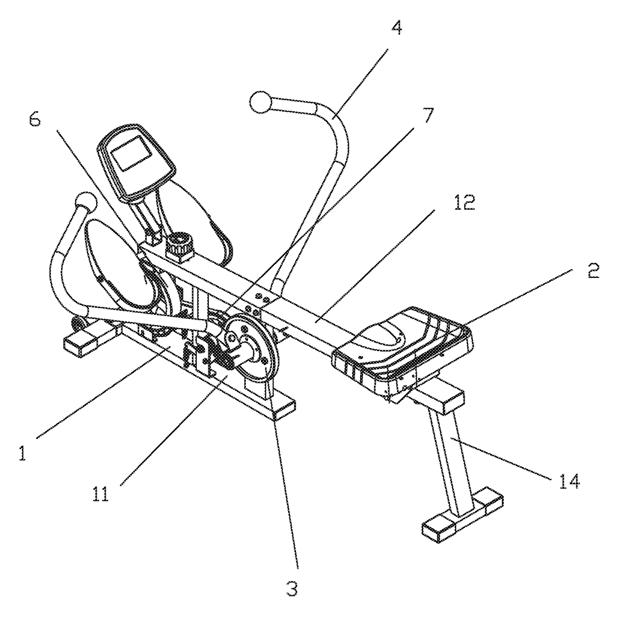
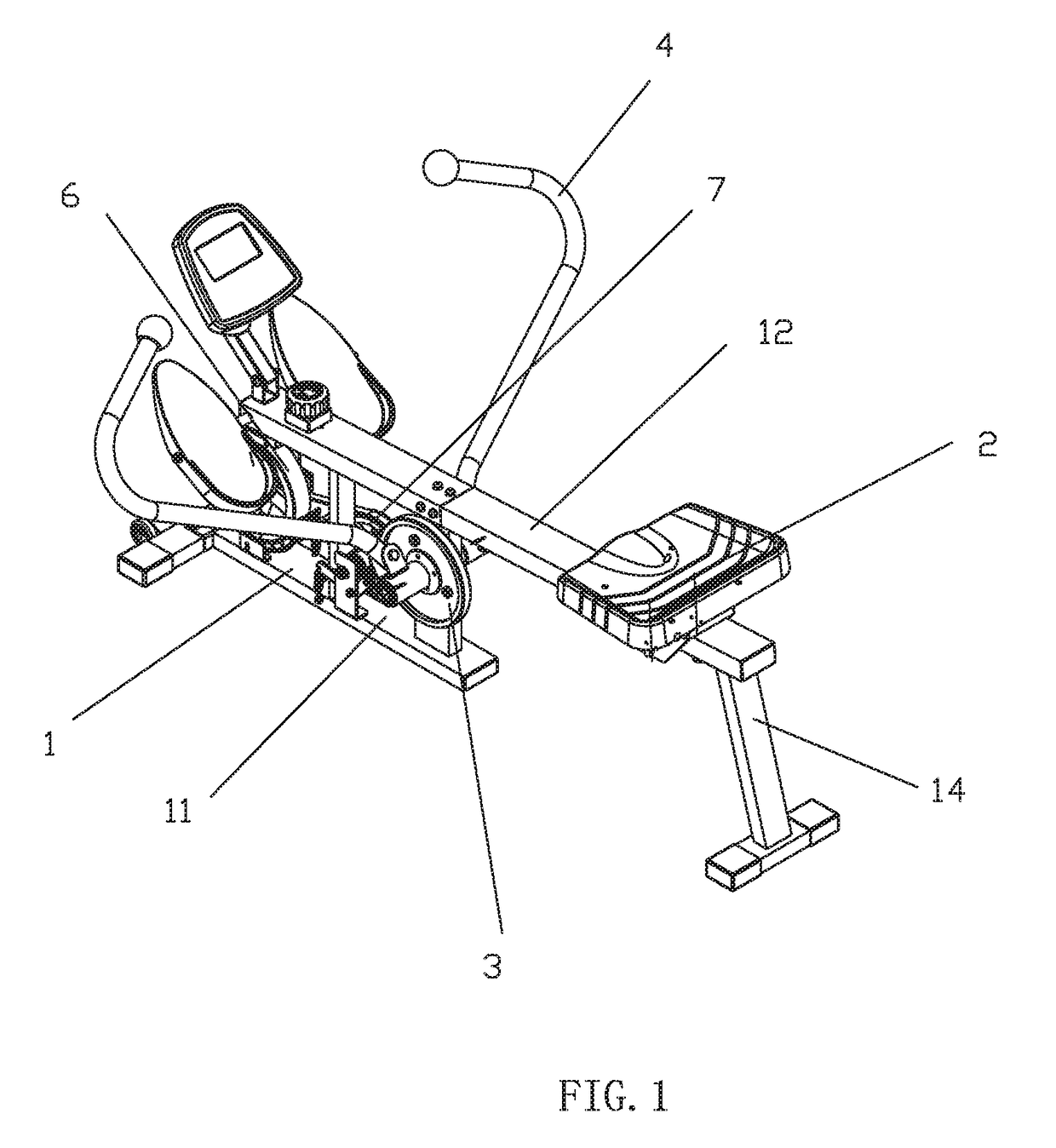
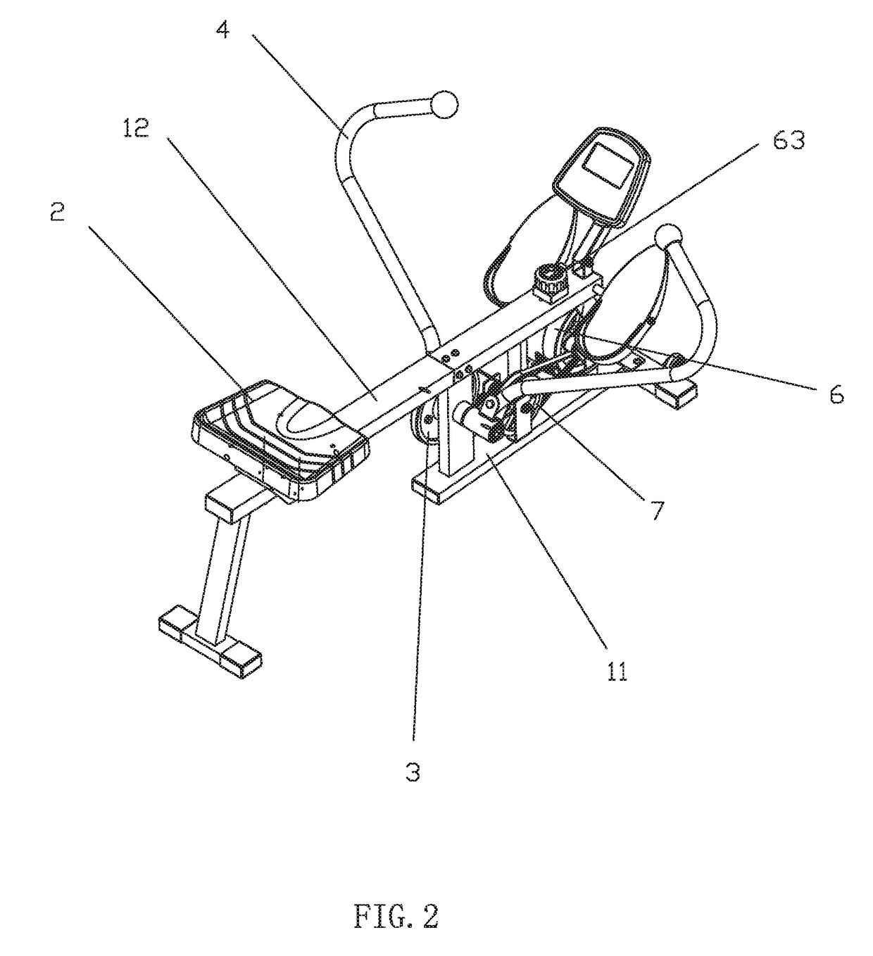
[0047]Referring to FIGS. 1-10, a rowing machine of the present invention comprises:

[0048]a base 1 with a rack 11 and a slope rail 12;

[0049]a seat cushion 2 slidably coupled to the rail 12;

[0050]a rotating plate 3 with a fixing rotating shaft 31 rotatably assembled to the rack 11 through the rotating shaf 31;

[0051]two oar components 4 respectively connected to the two ends of the rotating shaft 31 by unilateral bearings 51 in universal joining way to unilaterally drive the rotating plate 3 to rotate when swinging;

[0052]a rotation damping mechanism 6 with strength adjustable and assembled to the rack 11; and

[0053]an acceleration type transition transmission mechanism 7 assembled between the rotating plate 3 and the damping mechanism 6 to drive a damping wheel 61 of the damping mechanism when the rotating plate 3 rotates.

[0054]The base 1 further comprises a front base pipe component 13 and a rear base pipe component 14, the front base pipe component 13 is connected to the front portion...

second embodiment

[0063]Referring to FIG. 11, the difference of a rowing machine of this embodiment from the first embodiment is the damping mechanism. The damping mechanism further comprises an electromagnetic component 64, the damping wheel 61 is a magnetic control wheel, the electromagnetic component 64 is assembled to the rack 11 and is coupled to the magnetic control wheel, the electromagnetic component 64 is connected to an electronic control instrument by a wire.

[0064]The damping strength of the damping wheel 61 can be adjusted by adjusting the current of the electromagnetic component 64.

third embodiment

[0065]Referring to FIG. 12, the difference of a rowing machine of this embodiment from the first embodiment is the damping mechanism. The damping mechanism is a windage damping mechanism; the damping wheel is a fan blade 65.


PUM


Abstract

A rowing machine has a base, a seat, a rotating plate, two oar components, a damping mechanism and a transmission mechanism; the base with a rack and a slope rail; the seat cushion slidably coupled to the rail; the rotating plate with a fixing rotating shaft rotatably assembled to the rack through the rotating shaft; two oar components respectively connected to the two ends of the rotating shaft by unilateral bearings in universal joining way to unilaterally drive the rotating plate to rotate when swinging; the rotation damping mechanism is assembled to the rack; the transmission mechanism assembled between the rotating plate and the damping mechanism to drive a damping wheel of the damping mechanism when the rotating plate rotates.

Description

FIELD OF THE INVENTION[0001]The present invention relates to fitness equipment, particularly to a rowing machine.BACKGROUND OF THE INVENTION[0002]Rowing machine is also called boating machine which is a kind of fitness equipment simulating boating. The traditional rowing machine mainly adopts with a left and right handles and an oil cylinder mechanism. The left and right handles are respectively connected to the oil cylinder mechanism, and the damping effect of the left and right handles in the shaking process is realized by using the oil cylinder mechanism. This kind of rowing machine with oil cylinder mechanism has disadvantages of high producing cost, easy leakage problem of the oil cylinder and pollution of environment. The rowing machine in current technology (as disclosed in the Chinese patent database with publishing number CN203425451U) has the handle connected to a webbing, the webbing is connected to a pulley, and the pulley drives the damping wheel. When the user pulls th...

Claims


Application Information

Patent Timeline
Patent Type & Authority Applications(United States)
IPC IPC(8): A63B22/00A63B24/00A63B21/005A63B23/035A63B23/02A63B21/008A63B21/00A63B23/12
CPCA63B22/0076A63B21/0084A63B21/0088A63B21/005A63B21/154A63B21/4039A63B2022/0084A63B21/4035A63B22/001A63B23/0233A63B23/03575A63B24/0087A63B23/12A63B21/4045A61H2015/0014A61H2201/0149A61H2201/1284A61H2201/1695A61H2205/081A63B21/00069A63B21/0051A63B21/023A63B21/0455A63B21/15A63B21/151A63B21/225A63B22/0087A63B22/0089A63B71/0622A63B2210/50
Inventor HOU, YANWEI
Owner XIAMEN AOLRO TECH
Why Eureka
Try Eureka