Light emitting device

a technology of light-emitting devices and light-emitting elements, which is applied in the direction of solid-state devices, semiconductor devices for light sources, lighting and heating apparatus, etc., can solve the problems of difficult to prevent a decrease in emission intensity, and achieve the effect of improving the emission intensity of light-emitting elements

Active Publication Date: 2017-12-21
CITIZEN ELECTRONICS CO LTD +1
View PDF11 Cites 5 Cited by
  • Summary
  • Abstract
  • Description
  • Claims
  • Application Information

AI Technical Summary

Benefits of technology

[0013]In a light-emitting device in which light-emitting elements are sealed with a sealing resin in which a phosphor is dispersed, the phosphor generates heat by light from the light-emitting elements, and the emission intensity of the light-emitting elements is decreased by the heat. Even when a metal substrate which excels in heat dissipation is used as a mounting substrate of the light-emitting elements, the heat by the phosphor at a position away from the mounting substrate is not sufficiently transferred to the mounting substrate, and thus, the heat is easy to be accumulated in the sealing resin, and it is still difficult to prevent a decrease in the emission intensity.
[0014]It is an object of the present invention to provide a light-emitting device in which the emission intensity of light-emitting elements is improved by making heat generated by light emission of the light-emitting elements be effectively released.
[0024]In addition, provided is a light-emitting device including a substrate having a frame provided on an outer edge thereof, light-emitting elements arranged on the substrate, a sealing resin filled in the frame to seal the light-emitting elements, wherein the substrate is provided with a deformation preventing member preventing the sealing resin from being dented to a certain depth or more when the sealing resin is dented due to pressure from above.
[0033]According to the above light-emitting device, it is possible to make heat generated by light emission of light-emitting elements be effectively released, and thereby improve the emission intensity of the light-emitting elements.

Problems solved by technology

Even when a metal substrate which excels in heat dissipation is used as a mounting substrate of the light-emitting elements, the heat by the phosphor at a position away from the mounting substrate is not sufficiently transferred to the mounting substrate, and thus, the heat is easy to be accumulated in the sealing resin, and it is still difficult to prevent a decrease in the emission intensity.

Method used


Image

  • Light emitting device
  • Light emitting device
  • Light emitting device

Examples


Embodiment Construction

[0074]Hereinafter, with reference to the accompanying drawings, a light-emitting device will be explained in detail. However, it should be noted that the present invention is not limited to the drawings or the embodiments described below.

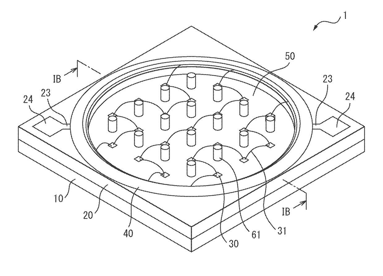
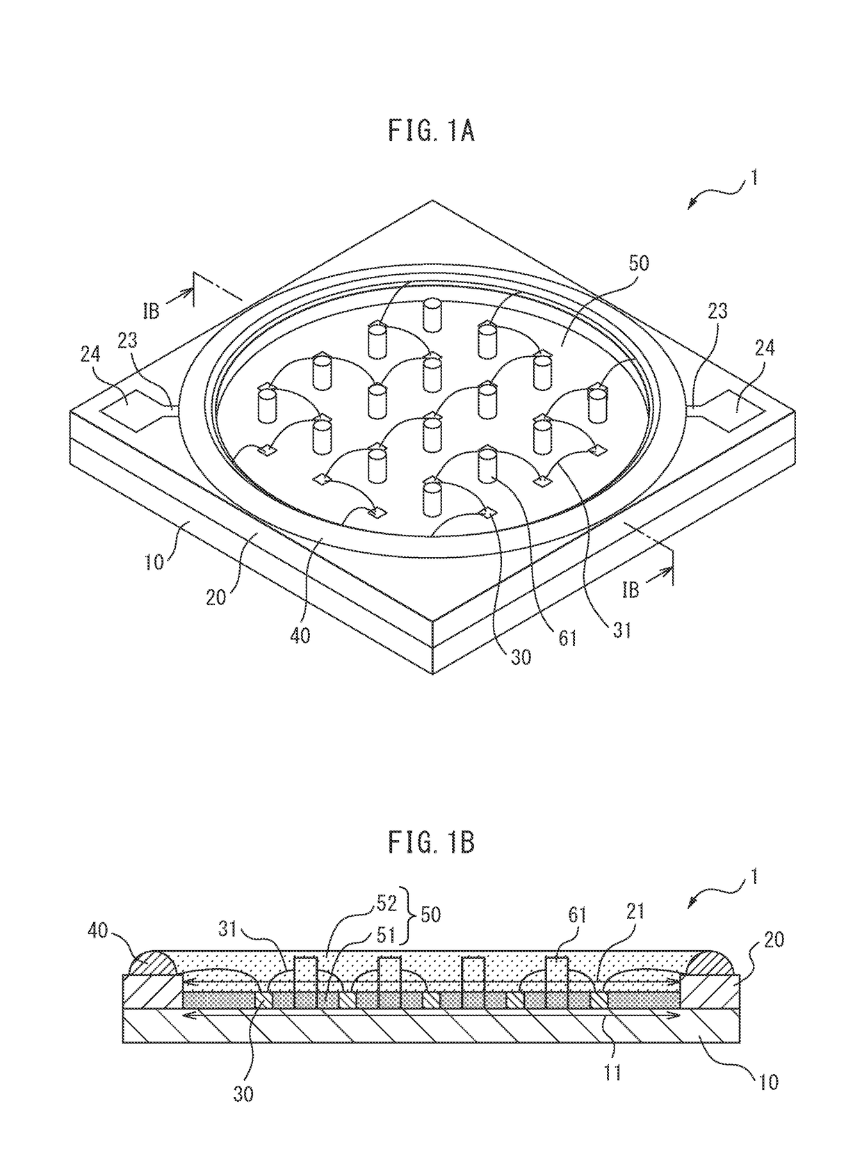
[0075]FIG. 1A is a perspective view of a light-emitting device 1 as a finished product, and FIG. 1B is a cross-sectional view of the light-emitting device 1 taken along the line IB-IB of FIG. 1A. The light-emitting device 1 includes LED elements as light-emitting elements, and is used as various lighting devices, such as LEDs for lighting and LED light bulbs. The light-emitting device 1 includes, as main components, a mounting substrate 10, a circuit substrate 20, LED elements 30, a resin frame 40, a sealing resin 50, and heat transfer members 61.

[0076]The mounting substrate 10 is a metal substrate which has a square shape, as an example, and has, at the center on the upper surface thereof, a circular mounting region 11 on which the LED elements 30 ...


PUM


Abstract

A light-emitting device in which the emission intensity of light-emitting elements is improved by making heat generated by light emission of the light-emitting elements be effectively released is provided. The light-emitting device includes a mounting substrate including a mounting region, light-emitting elements mounted on the mounting region, a sealing resin which contains a phosphor and integrally seals the light-emitting elements, and at least one heat transfer member which is arranged among the light-emitting elements on the mounting region, is embedded in the sealing resin, and has a higher thermal conductivity than the sealing resin.

Description

CROSS REFERENCE TO RELATED APPLICATIONS[0001]This is the U.S. National Phase application of PCT / JP2015 / 084708, filed Dec. 10, 2015, which claims priority to Japanese Patent Application Nos. 2014-250850, filed Dec. 11, 2014, and 2015-112330, filed June. 2, 2015, the disclosures of each of these applications being incorporated herein by reference in their entireties for all purposes.TECHNICAL FIELD[0002]The present invention relates to a light-emitting device.BACKGROUND ART[0003]A COB (Chip On Board) light-emitting device in which light-emitting elements, such as LED (light-emitting diode) elements, are mounted on a general-purpose substrate, such as a ceramic substrate or a metal substrate, is known. In such a light-emitting device, white light or the like is obtained depending on the intended use by sealing, for example, LED elements that emit blue light with a resin containing a phosphor, and mixing light obtained by exciting the phosphor with the light from the LED elements.[0004]...

Claims


Application Information

Patent Timeline
Patent Type & Authority Applications(United States)
IPC IPC(8): H01L33/50H01L33/62H01L33/56H01L33/64H01L25/075
CPCH01L33/507H01L25/0753H01L33/56H01L33/62H01L33/644F21V31/00F21V31/04F21K9/00F21S2/00F21V19/00F21V23/00H01L33/48H01L2924/181H01L2224/48091H01L2224/48137H01L2224/48139H01L2924/00012H01L2924/00014
Inventor FUKASAWA, KOICHIOYAMADA, NODOKA
Owner CITIZEN ELECTRONICS CO LTD
Why Eureka
Try Eureka