Liquid Cooling Radiation System and Liquid Radiator Thereof

a radiation system and liquid cooling technology, applied in the direction of lighting and heating apparatus, instruments, semiconductor/solid-state device details, etc., can solve the problems of large space utilization, inconvenience in installation and operation, and very limited application, so as to prolong the motor life, increase the heat exchange effect, and reduce the space requirement

Active Publication Date: 2017-12-21
APALTEK CO LTD
View PDF58 Cites 29 Cited by
  • Summary
  • Abstract
  • Description
  • Claims
  • Application Information

AI Technical Summary

Benefits of technology

[0018]The present invention is based on the existing product and employs an integral arrangement of the pump body and the heat dissipating device. In this way, the pump body is positioned in the middle of the radiator unit. The fan for heat dissipation not only is used to bring away the heat from the radiator, but also to bring away the heat generated from the pump power device. Accordingly, the motor life is prolonged. Also, the space requirement is greatly reduced. The pump body is connected to four inlet and eight outlet cooling tubes, which greatly increases the heat exchange effect. The power fan blades has five fan blades with a silicon steel sheet surrou...

Problems solved by technology

The drawback of this design is that the three components are assembled and affixed by external connection through connecting pipes, thus a relatively large space is utilized and its installation and operation is inconvenience.
In view of the relatively high installation requirement for space and poor flexibility in installation, its application is very limited.
This integration arrangement will lead to the heat absorbing device having a size which is not s...

Method used


Image

  • Liquid Cooling Radiation System and Liquid Radiator Thereof
  • Liquid Cooling Radiation System and Liquid Radiator Thereof
  • Liquid Cooling Radiation System and Liquid Radiator Thereof

Examples


Embodiment Construction

[0026]In order to make the objects, technical solutions and advantages of the present invention more clearly understood, the various embodiments are further described with the accompanying drawings in the followings. These drawings figures form a part of the embodiment, wherein the embodiment in which the present invention may be realized is described. It is to be understood that other embodiments may be used, or structural and functional modifications may be made to the embodiments described herein without departing from the scope and spirit of the present invention.

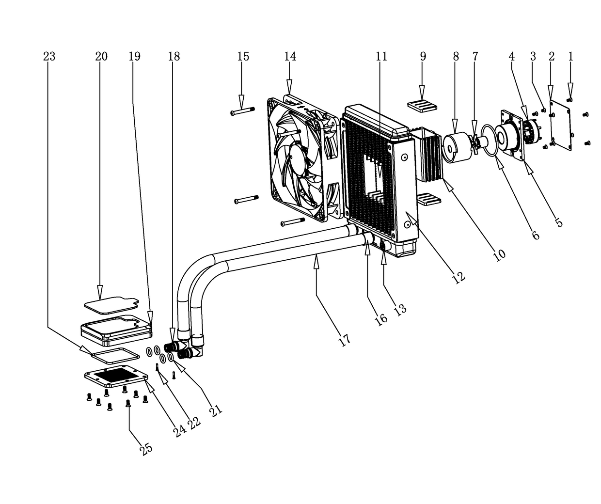
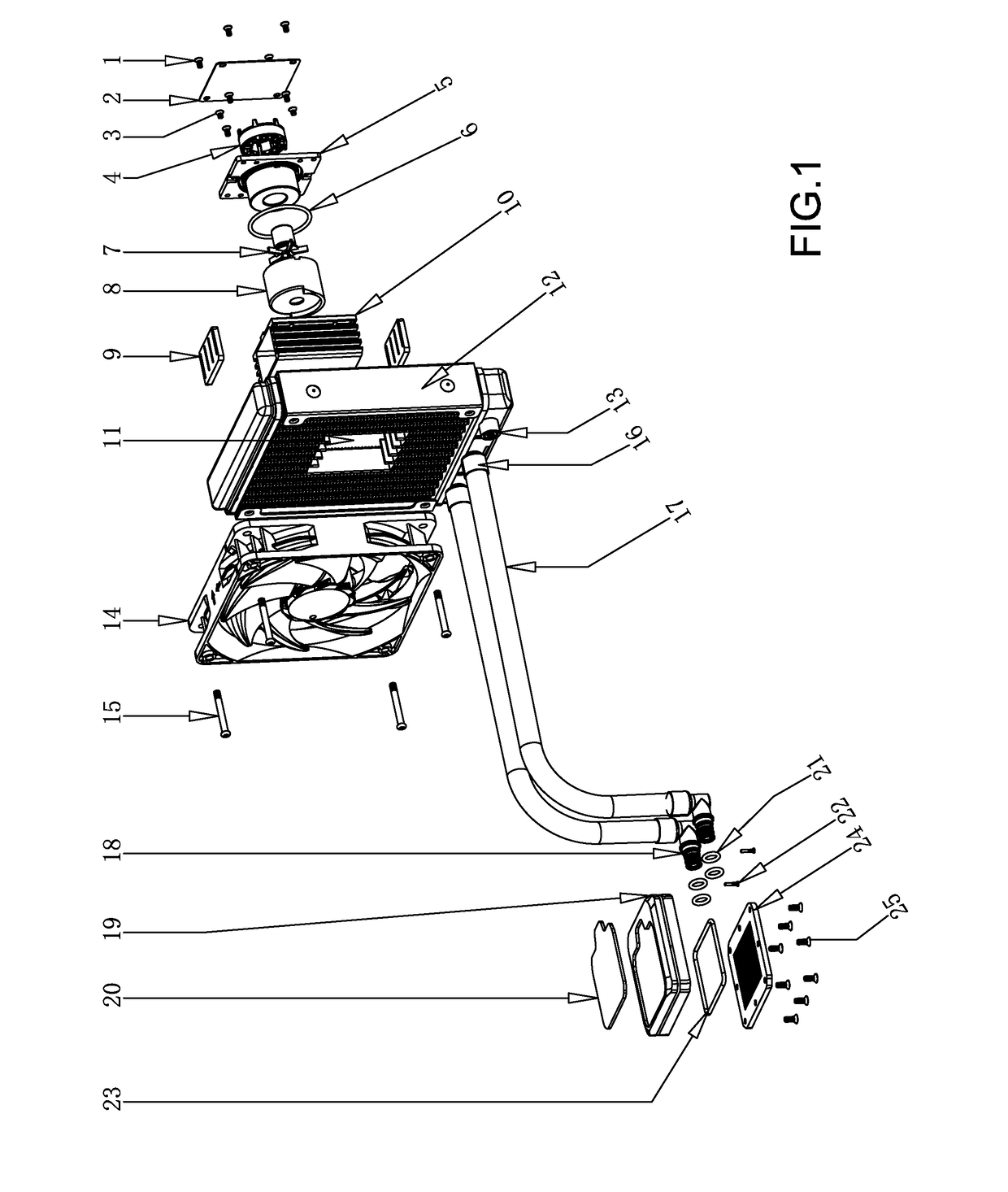
[0027]According to FIG. 1 of the drawings, an exploded view of the product as a whole according to a preferred embodiment of the present invention is illustrated; in conjunction with FIG. 1 and according to this embodiment, water is used as the coolant, the entire liquid cooling system comprises a fan 14, a radiator unit 12, a water pump body, a tube unit 17, a water-cooled head body, wherein the radiator unit 12 compri...


PUM


Abstract

Disclosed is a liquid cooling radiation system. The technical solution used by the present invention to solve the technical problem is: the liquid cooling radiation system comprises: a radiation device, comprising cooling pipes and a radiation structure device arranged on the cooling pipes; a pumping device, integrally arranged between the cooling pipes and generating power so that a coolant circulates within the cooling pipes; a heat absorption device, attached to a heating device and having a heat conduction effect with the heating device; a pipeline, used for connecting the radiation device and the heat absorption device. On the basis of existing products, the present invention utilises a solution wherein a liquid pump main body and a radiator are integrally arranged together. Thus, the radiation of a fan is used to take away heat on the radiator and heat generated by a pump power main body (i.e. a motor) itself is also taken away, thereby extending the service life of the motor. In addition, the occupied space is significantly reduced, the heat transfer effect is significantly improved, and the production and assembly costs are reduced, so that product assembly is convenient and efficiency is high.

Description

BACKGROUND OF THE PRESENT INVENTIONField of Invention[0001]The present invention relates to a liquid cooling system, and more particularly to a liquid cooling system which includes a pump body integrally arranged inside a heat dissipating arrangement.Description of Related Arts[0002]At present, water-cooled radiators are commonly used as the cooling devices for cooling down devices such as computer CPU, graphic cards, chips of electronic equipment and are basically consist of three major components, which are heat absorbing device, pumping power device and heat dissipating device. The three components are connected to form a closed loop for liquid circulation in which the heat absorbing device is connected to the heat dissipating device while the pumping power device provides power to liquid circulation in the loop. The drawback of this design is that the three components are assembled and affixed by external connection through connecting pipes, thus a relatively large space is util...

Claims


Application Information

Patent Timeline
IPC IPC(8): H05K7/20G06F1/20
CPCH05K7/20272H05K7/20263G06F2200/201G06F1/20H05K7/20409F28D1/05375F28D2001/028F28D2021/0031H01L21/4882H01L23/3672H01L23/467H01L23/473F28F2250/08G06F1/203H01L23/40H01L23/46H01L23/4735H01L2924/0002H05K7/20
Inventor XIAO, QINENG
Owner APALTEK CO LTD
Why Eureka
Try Eureka