Abrasion resistant film for biocontainers

a biocontainer and abrasion resistance technology, applied in the direction of fluid-tightness measurement, synthetic resin layered products, packaging, etc., can solve the problems of reducing the service life of the biocontainer, the chance of abrasion, puncture or abrasion to occur to the biocontainer, and the loss of the biocontainer and its contents. , to achieve the effect of reducing system cost and complexity and reducing the potential for sh

Active Publication Date: 2017-12-28
MILLIPORE CORP
View PDF6 Cites 6 Cited by
  • Summary
  • Abstract
  • Description
  • Claims
  • Application Information

AI Technical Summary

Benefits of technology

[0068]If desired, one can maintain the pressure within the bag 60 constant by supplying additional air pressure as the liquid is dispensed. This allows one to maintain the desired head pressure within the bag 60 so that the liquid can be fully dispensed at a constant rate from the bag 60. Alternatively, one can simply apply a fixed head pressure that reduces as liquid is dispensed from the bag 60.
[0069]In either embodiment, the use of valves, check valves, clamps, pressure gauges, windows and the like can also be used to maintain the system in its desired state and providing the desired dispensing or movement of liquid 68 out of the bag 60 as needed. All of these elements are well known to one of ordinary skill in the art.
[0070]Either embodiment eliminates the need for pumps to move liquid out of the bag 60. This can be of advantage in reducing system cost and complexity and in reducing the potential for shear damage to shear sensitive products that are dispensed from the bag 60 such as various protein solutions and the like.
[0071]In a further embodiment of the present invention, the bag 100 may contain one or more grommets or eyes 102 especially at its upper corners 104 so that the bag 100 can be simply hang from a hook or preferably a carrier as shown in FIG. 7. As the substrate makes the bag 100 more resilient and self-supportive, there is less of a need for a rigid enclosed support vessel such as a vat or bin as is typically used with such containers. This allows one to use a simple framework 106 as shown in FIG. 8. As shown in FIG. 8, the framework 106 is formed of a base 108, and at least four vertically extending rods 110.
[0072]Preferably, and as shown, near the top ends 112 of each of the rods 110 are secondary substantially horizontal rods 114. Each secondary substantially horizontal rod 114 is connected to the adjacent rods 110 to complete the framework 106.
[0073]In either embodiment the grommets 102 are attached to the top ends 112 and the bag 100 is allowed to hang inside the framework 106 as shown in FIG. 9.

Problems solved by technology

Biocontainers are generally inspected and gross leak tested for defects before they are shipped to the user, however, current films in biocontainers lack the strength, toughness and durability to survive the multiple manipulation steps used in atypical biotech facility to unpackage, install and use such a biocontainer.
Due mostly to operator handling there is still the chance for a cut, puncture or abrasion to occur to the biocontainer.
This can lead to not only loss of the biocontainer but also of its contents which in the case of pharmaceuticals especially biopharmaceuticals represents a significant monetary loss.

Method used


Image

  • Abrasion resistant film for biocontainers
  • Abrasion resistant film for biocontainers
  • Abrasion resistant film for biocontainers

Examples


example 1

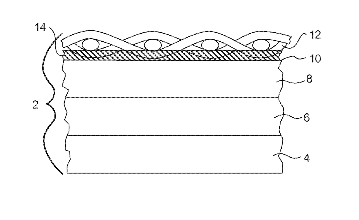
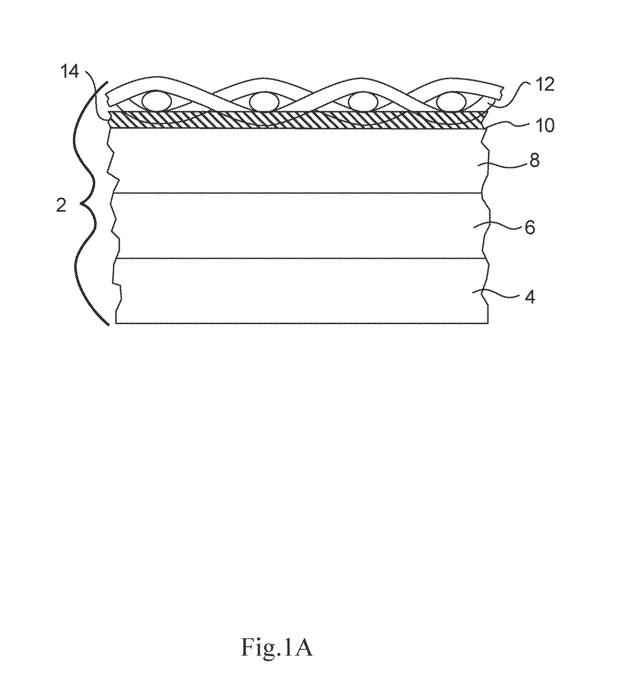
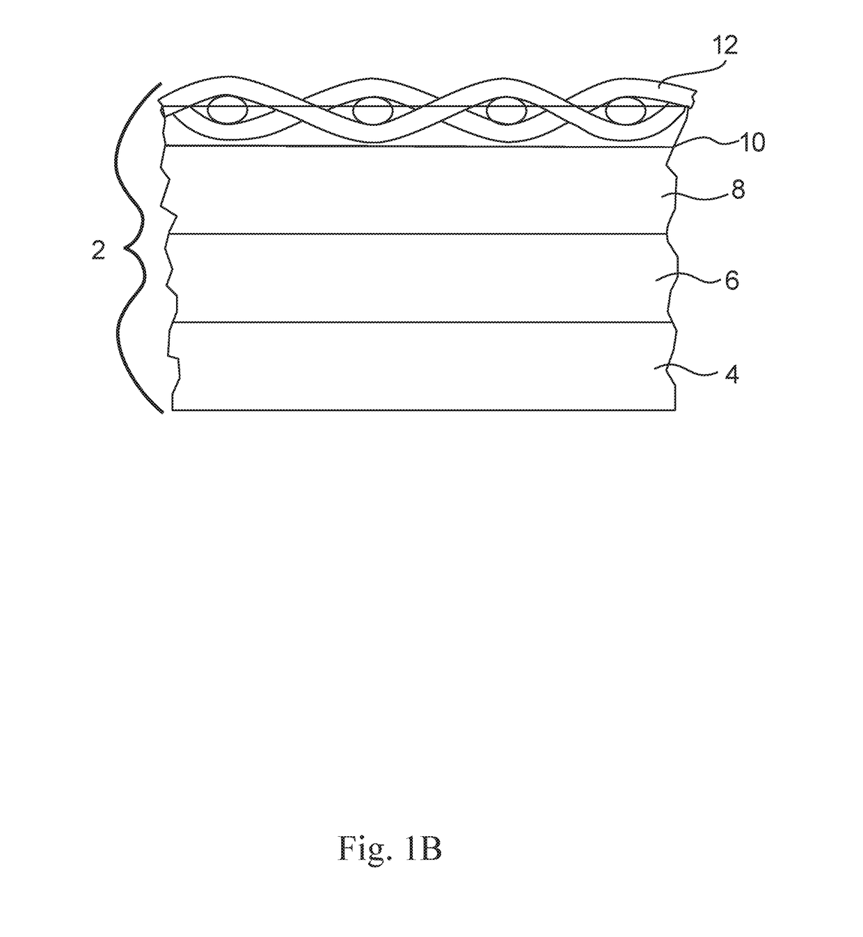
[0075]Three typical Single Use biocontainer films were compared to a composite substrate, made in according to the present invention, for abrasion and puncture resistance.

[0076]The substrate when used was extrusion coated onto the outer surface of the film using a polyethylene, copolymer attachment layer The attachment layer as embedded in the substrate was heated to a temperature of 500 degrees (F.)+ / −20 degrees (F.) (260° C.+ / −11° C.) and laminated under 10 pounds per square inch pressure by a roller.

[0077]A Taber Industries Linear Abrasion Tester was procured and a strip of each sample of 1.5 inch by 3 inch (3.8 cm×7.6 cm) was placed between the stylus and backing cylinder. Both the stylus and backing cylinder were capable of carrying an electrical current. The stylus was brought into contact with the surface of the sample or Control and reciprocated linearly over the surface of the material being tested with a stroke of 4 inches and at a cycle rate of 30 cycles per minute until ...

example 2

[0080]A biocontainer was formed using the substrate / film material according to the embodiment of Example 1. A window was formed in it by simply cutting out the window shape in the substrate before it was attached to the film.

example 3

[0081]A first biocontainer was formed using a transparent substrate material (nylon woven fabric) which was laminated to the film material according to the embodiment of Example 1. A window formed in it by simply heating and compressing a window shape in the substrate before it was attached to the film. A second biocontainer was formed using a transparent substrate material (polyester nonwoven) which was laminated to the film material according to the embodiment of Example 1. A window formed in it by simply heating and compressing a window shape in the substrate before it was attached to the film.


PUM

PropertyMeasurementUnit
volumeaaaaaaaaaa
pressureaaaaaaaaaa
pressuresaaaaaaaaaa

Abstract

A biocontainer film enhanced with an abrasion resistant or “cut-proof” substrate. Such substrates can be combined with current biocontainer materials, via various techniques of embedding, coextrusion or laminating, to maintain the cleanliness and low extractables already validated for biotech manufacturing. The substrate of choice may be constructed from materials known to be more resistant to abrasion and sharp razor type cuts or from materials oriented in such a way to prevent puncture to occur. The new substrate must also be flexible to allow for typical folding as demonstrated by current packaging practices. The new substrate may be constructed from materials other than polymers such as metal, glass or carbon or in combination with polymers. A non-constrained pressure test is also disclosed.

Description

[0001]The present invention relates to abrasion resistant films. More particularly it relates to abrasion resistant films for biocontainers.BACKGROUND OF THE INVENTION[0002]The use of single use bags and other biocontainers is growing in the pharmaceutical and biopharmaceutical business. These bags replace stainless tanks, totes and bins for the processing and transportation of liquids and solids such as raw materials, intermediates and finished goods.[0003]Such film are typically multilayered plastic film structures. They are typically laminates of 4 or more layers (generally between 4 and 10 layers). They generally have 3 or more zones or layers, an inner contact zone which is in contact with the liquid within the bag and which is one or more layers of a generally inert material such as polyethylene that is not likely to release extractables, such as oils or fillers into the content of the bag; an intermediate zone, which often has one or more gas impermeable layers such as ethyle...

Claims


Application Information

Patent Timeline
Patent Type & Authority Applications(United States)
IPC IPC(8): B32B5/02B65D75/58B32B27/08B32B27/12B32B27/32B32B27/40G01M3/32B65D65/40B01L3/00
CPCB32B5/024B32B5/022B32B27/08B32B27/12B32B27/32B32B27/40B65D65/40B65D75/58G01M3/3272B01L3/508B32B2262/0253B32B2262/0261B32B2262/0276B32B2262/103B32B2262/106B32B2307/554B32B2439/40B32B2439/80B01L2300/0887B01L2300/16B32B5/02B32B27/34B65D31/04B65D33/04B32B2262/0269B32B2307/7242B65D2275/00B32B2260/046B32B2262/101B32B2262/0284C12M23/14C12M23/20B32B1/02B32B7/12C12M23/00B32B2307/7244
Inventor DECOSTE, DAVIDCIANCIOLO, JOSEPHFURBUSH, MICHAELSARAGOSA, JOHN
Owner MILLIPORE CORP
Why Eureka
Try Eureka