Wrinkle Reduction in Formed Composite Laminates

Active Publication Date: 2017-12-28
THE BOEING CO
View PDF6 Cites 4 Cited by
  • Summary
  • Abstract
  • Description
  • Claims
  • Application Information

AI Technical Summary

Benefits of technology

[0004]The disclosure relates in general to fabrication of composite laminate parts having contoured geometries and high aspect rat

Problems solved by technology

The problem of ply wrinkling can be more pronounced where the part has a large number of plies and/or contains joggles or aggressive ply ramps along its length.
Ply wrinkling is undesirable.
In some applications, parts can be reworked to reduce or eliminate ply wrinkling, however the rework adds to labor costs and may red

Method used


Image

  • Wrinkle Reduction in Formed Composite Laminates
  • Wrinkle Reduction in Formed Composite Laminates
  • Wrinkle Reduction in Formed Composite Laminates

Examples


Example

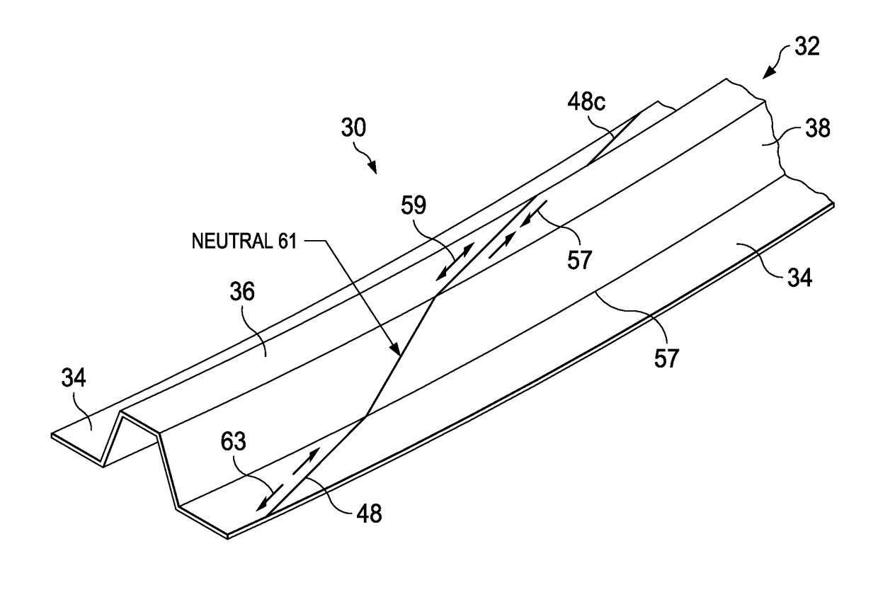
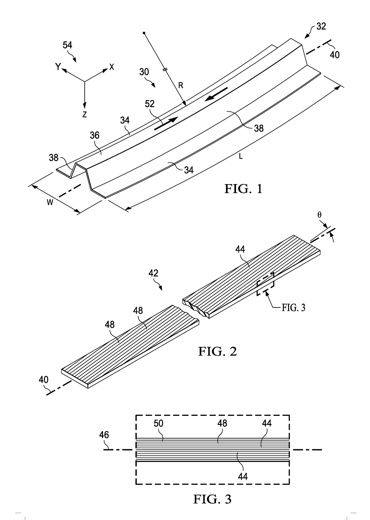
[0038]Referring first to FIG. 1, a composite laminate part 30 is contoured along its length L and has a radius of curvature R. In the illustrated example, the part 30 is a stringer 30, also referred to herein as a stiffener 30, used to transmit loads in a structure such as the airframe of an aircraft, however principles of the disclosed embodiments may be used in the fabrication of a wide range of other types of contoured composite parts, especially structural stiffeners, having various cross sectional shapes. As used herein “contour” and “contoured” are each used in its broadest sense, and includes but is not limited to curvatures in any portion, or throughout the length of the part 30. “Contour” and “contoured” also include curvatures or other geometric features having either a constant or a changing radius of curvature, as well as local changes in geometry such as, without limitation, joggles. The stiffener 30 has a hat section 32 defined by a cap 36 and a pair of webs 38. The we...


PUM

PropertyMeasurementUnit
Angleaaaaaaaaaa
Angleaaaaaaaaaa
Angleaaaaaaaaaa

Abstract

Wrinkling of a contoured composite laminate part during forming to contour is reduced by using laminate plies having off-angle reinforcing fibers that provide the part with primary axial strength along a major axis of loading.

Description

BACKGROUND INFORMATION1. Field[0001]The present disclosure generally relates to fabrication of contoured composite laminates, especially those having high aspect ratios, and deals more particularly with a method of reducing wrinkling of a laminate during forming to a desired contour.2. Background[0002]In one process for producing elongated composite laminate parts having contoured geometries, unidirectional prepreg plies are laid up, either by hand or using automated layup equipment, to form a flat laminate stack. In an initial forming operation, a pair of matched dies punch form the flat stack into a straight part having a desired cross-sectional shape. In a secondary forming operation, the part is formed onto a contoured forming tool which imparts a desired contour to the part along its length. As a result of these two forming operations, the part has contours along two axes.[0003]Traditional laminate layups typically use a combination of 0°, 45° and 90° plies. When using these tr...

Claims


Application Information

Patent Timeline
IPC IPC(8): B32B38/18B32B5/26B32B7/00B32B7/03
CPCB32B38/1866B32B7/005B32B2305/08B32B2307/514B32B5/26B29L2031/001B29C70/34B29D99/0003B29C70/207G06F2113/24G06F2113/26G06F30/20B32B7/03B32B38/18B32B41/00B32B2038/0072
Inventor BLOM-SCHIEBER, ADRIANA WILLEMPJE
Owner THE BOEING CO
Why Eureka
Try Eureka