Centrifugal compressor assembly and method of operation with an airconditioner

a centrifugal compressor and air conditioner technology, which is applied in the direction of liquid cushion bearings, machines/engines, liquid fuel engines, etc., can solve the problems of increasing the efficiency of centrifugal compressors, increasing the radial and axial oscillation of rotors, and increasing the number of reynolds. , to achieve the effect of increasing bearing capacity, reducing radial and axial oscillation of rotors, and reducing the axial oscil

Active Publication Date: 2017-12-28
ZHEJIANG FLOWTECH INC
View PDF7 Cites 17 Cited by
  • Summary
  • Abstract
  • Description
  • Claims
  • Application Information

AI Technical Summary

Benefits of technology

[0014]The centrifugal compressor assembly is operational with smaller commercial air conditioning units, that minimizes rotational and axial oscillation of a rotor in the motor to reduce a tip clearance and a seal clearance for higher centrifugal compressor efficiency. In some embodiments, the centrifugal compressor assembly provides a motor that drives the compressor. The motor comprises a rotor. The motor uses radial aerostatic bearings to support and stabilize the rotation of the rotor. The motor also uses a thrust aerostatic bearing to support an axial force of the rotor. The radial aerostatic bearings and the thrust aerostatic bearing use a low-viscous vapor-liquid two-phase fluid as a lubricating medium.
[0015]The confinement of the rotor with the radial aerostatic bearing and thrust aerostatic bearings enables a clearance between a blade tip of an impeller and a volute to be reduced by a half; thereby increasing efficiency of the centrifugal compressor by at least 10%.
[0028]The present invention has multiple advantages. The centrifugal compressor of the assembly includes a motor. In the motor, a radial aerostatic bearing and a thrust aerostatic bearing, supporting a rotor of the motor, utilize porous aerostatic bearings using a low-viscous vapor-liquid two-phase refrigerant, so as to reduce radial and axial oscillation of the rotor. This enables a clearance between a blade tip of an impeller and a volute and a seal clearance to be reduced by a half (reduced to be less than 100 μm).
[0029]Consequently, the efficiency of the centrifugal compressor increases by at least 10%. Moreover, a liquid entering the radial aerostatic bearings and the thrust aerostatic bearing further functions to increase bearing capacities of the radial aerostatic bearings and the thrust aerostatic bearing and to cool the radial aerostatic bearings, the thrust aerostatic bearing, and the rotor of the motor.
[0031]Another objective is to reduce radial and axial oscillation of the rotor of the motor.

Problems solved by technology

Challenges that miniaturization of centrifugal compressors face are an increase in friction loss resulted from a decrease in Reynolds number, and increases in tip clearance and seal leakage loss.
Due to a manufacturing factor, an impeller of a small centrifuge must be an open impeller, and increases in tip clearance and seal leakage loss remarkably exceed an increase in friction loss.
A common journal oil bearing is subjected to a sharp increase in loss with an increase in rotation speed.
Although there is no friction loss, a magnetic bearing is subjected to substantial rotor oscillation in transitional processes such as startup, shutdown and load change, and therefore can hardly be applied to small air conditioning units without sacrificing the efficiency.
A traditional manner of adding a water jacket outside a motor housing can hardly cool a stator of the motor effectively, and is of no use in cooling the rotor.
A disadvantage of the static bearing is that an external pressurization device is required.
Meanwhile, in the bearing that rotates at a high speed, the high-viscous fluid generates a relatively large loss, causing the bearing to generate heat and to be damaged.
Therefore, the hydrostatic bearing is not suitable for a small high-speed centrifugal compressor.
The problem with these systems is that they are not operational with smaller commercial air conditioning units; they can't stabilize rotational and axial movements of a rotor in the motor to reduce a tip clearance and a seal clearance for higher centrifugal compressor efficiency.

Method used


Image

  • Centrifugal compressor assembly and method of operation with an airconditioner
  • Centrifugal compressor assembly and method of operation with an airconditioner
  • Centrifugal compressor assembly and method of operation with an airconditioner

Examples


Embodiment Construction

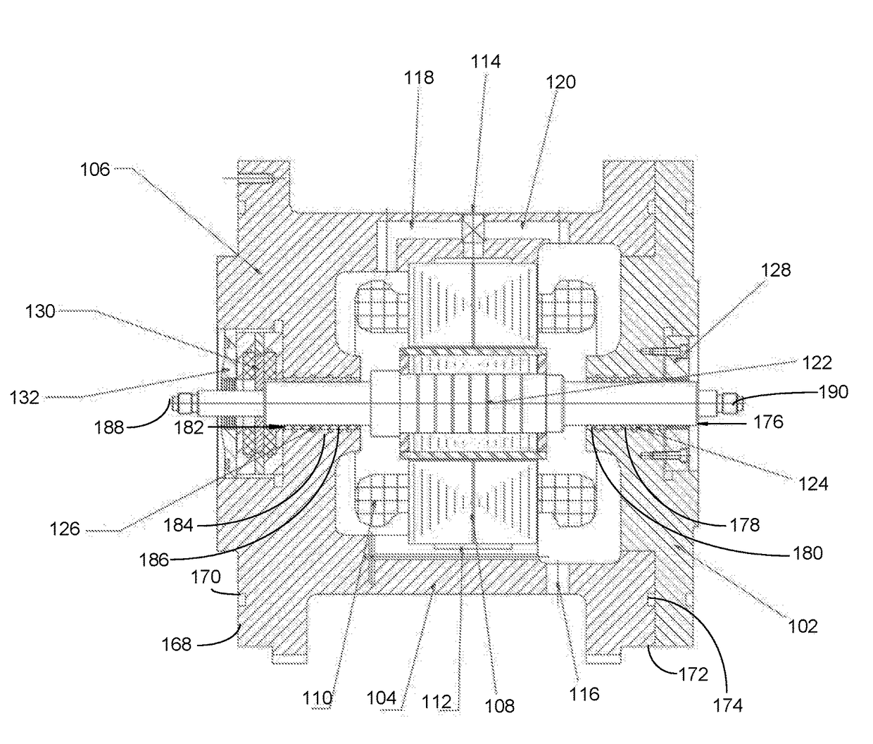
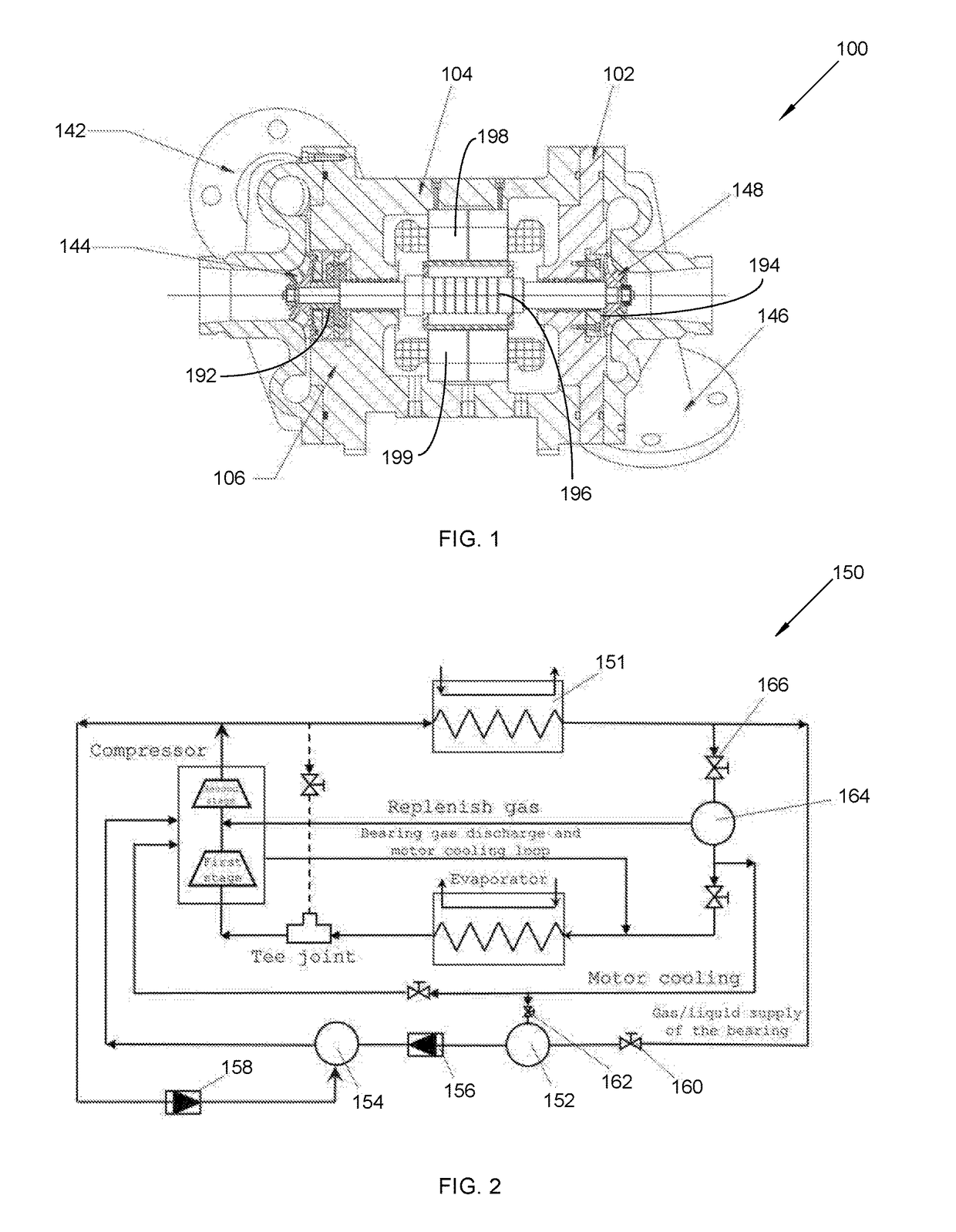
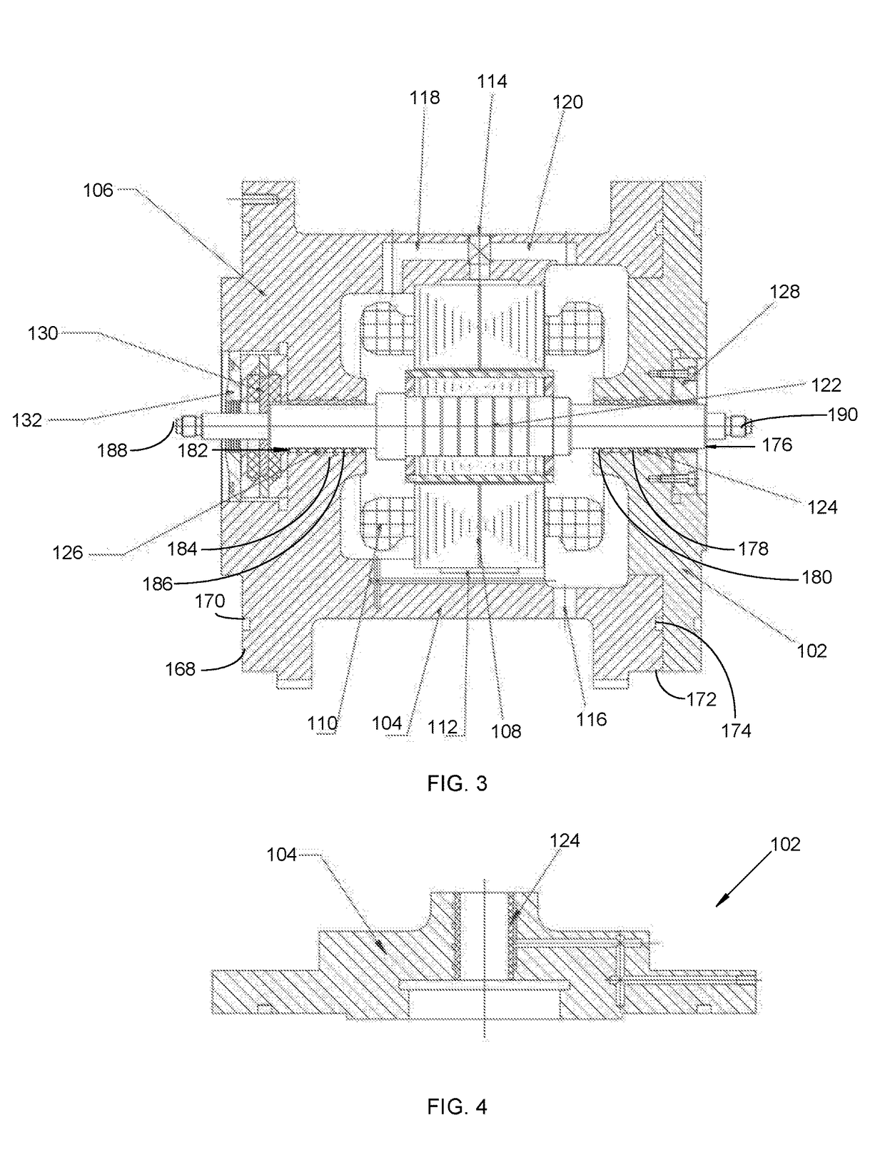
[0043]The following detailed description is merely exemplary in nature and is not intended to limit the described embodiments or the application and uses of the described embodiments. As used herein, the word “exemplary” or “illustrative” means “serving as an example, instance, or illustration.” Any implementation described herein as “exemplary” or “illustrative” is not necessarily to be construed as preferred or advantageous over other implementations. All of the implementations described below are exemplary implementations provided to enable persons skilled in the art to make or use the embodiments of the disclosure and are not intended to limit the scope of the disclosure, which is defined by the claims. For purposes of description herein, the terms “upper,”“lower,”“left,”“rear,”“right,”“front,”“vertical,”“horizontal,” and derivatives thereof shall relate to the invention as oriented in FIG. 1. Furthermore, there is no intention to be bound by any expressed or implied theory pres...


PUM


Abstract

A centrifugal compressor assembly and method of operation provides a motor that drives a first stage compressor. The motor comprises a rotor. The motor uses radial aerostatic bearings to stabilize rotation and axial displacement of the rotor. The motor also uses a thrust aerostatic bearing to balance an axial force of the rotor. The radial aerostatic bearings and the thrust aerostatic bearing use a low-viscous vapor-liquid two-phase fluid as a lubricating medium. The radial aerostatic bearings supports the rotor. The thrust aerostatic bearing uses porous aerostatic bearings that use a low-viscous vapor-liquid two-phase fluid, so as to reduce radial and axial oscillation of the rotor. This enables clearance between a blade tip of an impeller and a volute. This causes a seal clearance to be reduced by a half; thereby increasing efficiency of the centrifugal compressor by at least 10 percent.

Description

CROSS REFERENCE OF RELATED APPLICATIONS[0001]This application claims the benefits of Chinese application no. 201610518668.4, filed Jun. 28, 2016 and is titled the same.FIELD OF THE INVENTION[0002]The present invention relates generally to a centrifugal compressor assembly and method of operation with a water chiller. More so, the present invention relates to a centrifugal compressor that is operational with lower tonnage commercial air conditioning units, reduces a seal clearance by a half to increase efficiency of the centrifugal compressor by at least 10%, and stabilizes rotational and axial movement of a rotor in the motor.BACKGROUND OF THE INVENTION[0003]The following background information may present examples of specific aspects of the prior art (e.g., without limitation, approaches, facts, or common wisdom) that, while expected to be helpful to further educate the reader as to additional aspects of the prior art, is not to be construed as limiting the present invention, or an...

Claims


Application Information

Patent Timeline
Patent Type & Authority Applications(United States)
IPC IPC(8): F04D25/06F04D29/42F04D29/063F04D17/12F04D29/056F04D29/051F04D29/58F04D29/28
CPCF04D25/06F04D17/122F04D29/5806F04D29/056F04D29/4206F04D29/063F04D29/051F04D29/286F04D17/10F04D25/0606F04D29/0513H02K5/04H02K5/20F04D29/057F16C32/0618F16C32/064F16C32/0662F16C32/0696F16C2360/44
Inventor GU, FAHUAYUAN, PENGSONG, JIEJIEJI, WEIXING
Owner ZHEJIANG FLOWTECH INC
Why Eureka
Try Eureka