Synthetic Resin Retainer for Large Thrust Ball Bearings with Dry- and Wet-lubricant Management Systems

a technology of lubricant management system and retainer, which is applied in the field of ball bearings, can solve the problems of low production efficiency, low efficiency, and inability to meet the requirements of large-scale thrust ball bearings, and achieve the effects of reducing thermal induced effects on torque, sliding friction torque and dynamics, and minimizing radially transferring forces and retainer wear

Active Publication Date: 2017-12-28
ATEC CORP
View PDF0 Cites 4 Cited by
  • Summary
  • Abstract
  • Description
  • Claims
  • Application Information

AI Technical Summary

Benefits of technology

This patent describes a retainer for a bracket assembly. The retainer is made up of multiple circular arc pieces that hold balls. The retainer is designed to reduce thermal effects and friction between the segments and other bearing components. The retainer ends are rounded to minimize wear between segments. The retainer segments have guided features on the inner or bottom raceway shoulders, which minimizes instability and wear. The retainer pocket is circular, and the pocket / ball clearance is selected to account for part tolerances and thermal dimensional changes. The patent also mentions the use of liquid lubricants, and the proper choice of lubricants depends on various factors such as resistance torque, operating temperature, and speed. The retainer material is a molded synthetic resin with added fillers to increase strength and reduce wear rate. The amount of lubricant resupply is controlled based on the retainer material, interface clearances, and environmental operating conditions. Overall, this patent describes a retainer design that improves performance and durability.

Problems solved by technology

However, for large or larger thrust ball bearings, such large thrust ball bearings become very expensive to make or even become un-producible resulting from such distortions as excessive out-of-round, out-of-flatness, and torsional wrap.
In addition, for applications requiring extreme operating temperatures, such solid, single-piece retainers become a limiting factor due to thermal induced binding resulting from a coefficient of thermal expansion mismatch between the retainer and raceway materials.
In addition, conventional thrust ball bearing retainers are designed for use with liquid lubricants and may not work at all when liquid lubricants are not applicable or otherwise not to be used.
This results in limiting their use in applications where liquid lubricants are not applicable, such as where the ambient cold operating temperature is less than the pour point temperature of any liquid lubricant or where the ambient hot operating temperature exceeds the flash point temperature of any liquid lubricant or where the running torque excursions due to temperature levels do not meet a particular system capability or performance.

Method used


Image

  • Synthetic Resin Retainer for Large Thrust Ball Bearings with Dry- and Wet-lubricant Management Systems
  • Synthetic Resin Retainer for Large Thrust Ball Bearings with Dry- and Wet-lubricant Management Systems
  • Synthetic Resin Retainer for Large Thrust Ball Bearings with Dry- and Wet-lubricant Management Systems

Examples


Embodiment Construction

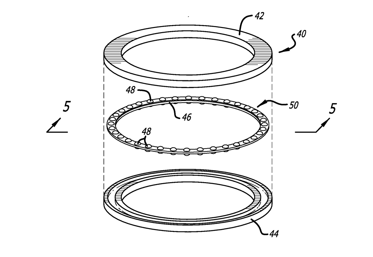
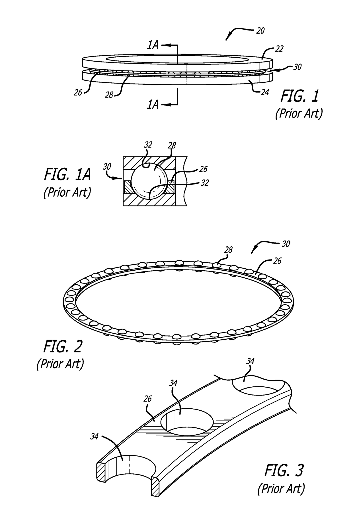
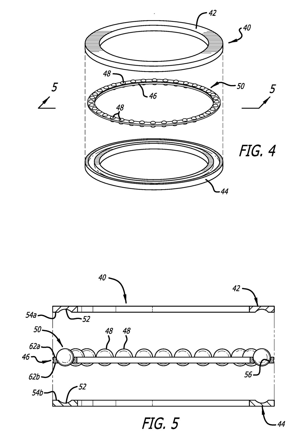
[0032]A conventional ball bearing assembly typically contains four basic components as depicted in FIGS. 1-3. Such a prior art assembly, denoted by indicium 20, comprises an outer or top ring 22, an inner or bottom ring 24, a ball retainer 26 (sometimes termed separator or cage) sandwiched between rings 22 and 24, rolling elements or ball bearings 28 held by the ball retainer. A lubricant (not shown) is often included. Ball retainer 26 and its contained rolling elements bearings 28 form an assembly 30 as best seen in FIG. 2. Each ring 22 and 24 include a race 32 as best shown in FIG. 1A for ball-bearings 28.

[0033]Bearing assembly 30 has its rolling elements 28 circumferentially spaced apart from one another and between outer or top ring 22 and inner or bottom ring 24. Thus, retainer 26 maintains the circumferential spacing between adjacent roller elements 28. The retainer is typically a single piece part with cylindrical holes or pockets 34.

[0034]A conventional thrust ball bearing r...


PUM

PropertyMeasurementUnit
torqueaaaaaaaaaa
sliding friction torqueaaaaaaaaaa
frictionaaaaaaaaaa

Abstract

A thrust ball bearing retainer a large size of bearings with the bearing raceways being modified using a surface enhancement process such as hard anodizing coating, which provides low friction coefficient and initial wear rate. The retainer material is selected to be molded, synthetic resin, self-lubricated material reinforced with carbon fiber, molybdenum disulfide, and PTPE. This lubrication system eliminates the thermal induced bearing torque effect due to viscosity. The retainer contains multiply segments with an inner race guided configuration, an alternative ball pocket cross section design and a ball pocket slotted configuration (1) to reduce the thermal induced effects due to coefficient of thermal expansion mismatch between the raceway and the retainer material (2) to enhance the producibility of the retainer due to out-of-round, out-of-flatness and torsional wrap, and (3) to reduce the manufacturing cost. The pocket design with an oval cross section instead of a circular cross section also reduces the localized thermal induced effect which would otherwise result in a pinching condition between the ball and the retainer. The alternative slotted retainer pocket design is used to increase the compliance between ball / pocket interfaces, which helps to reduce the dynamic induced effects. The ends of the retainer segments are designed to reduce the interactive transferring, circumferential force between two adjacent segments.

Description

CROSS-REFERENCE TO RELATED APPLICATION[0001]Not ApplicableREFERENCE REGARDING FEDERAL SPONSORSHIP[0002]Not ApplicableREFERENCE TO MICROFICHE APPENDIX[0003]Not ApplicableBACKGROUND OF THE INVENTION1. Field of the Invention[0004]This invention is related to ball bearings in general and, more particularly, to ball bearing retainers (also known as separators or cages) and a lubrication management system for large thrust ball bearings and to an integrated angular contact thrust bearing system.2. Description of Related Art and Other Considerations[0005]A conventional ball bearing assembly typically contains four basic components comprising an outer or top ring, an inner or bottom ring, a ball retainer (separators or cages) sandwiched between the two rings, rolling elements or ball bearings held by the ball retainer and a lubricant. The ball retainer and its contained rolling elements bearings form a ball bearing-retainer or bearing assembly. The bearing assembly has its rolling elements c...

Claims


Application Information

Patent Timeline
Patent Type & Authority Applications(United States)
IPC IPC(8): F16C19/10F16C33/38F16C33/66
CPCF16C19/10F16C33/3806F16C33/6622F16C33/6659F16C33/3887F16C33/3818F16C33/445F16C33/6651F16C33/6688F16C33/6696F16C2208/02F16C2208/04F16C2208/32F16C2223/70F16C2300/14Y02T10/86
Inventor TRAN, ANH
Owner ATEC CORP
Why Eureka
Try Eureka