Magnetic sensor and current sensor

a current sensor and magnetic sensor technology, applied in the field of magnetic sensors and current sensors, can solve the problems of reducing the bias generated in the free magnetic layer by the exchange coupling bias, and the detection accuracy of the gmr element may tend to decrease in some cases

Inactive Publication Date: 2017-12-28
ALPS ALPINE CO LTD
View PDF8 Cites 8 Cited by
  • Summary
  • Abstract
  • Description
  • Claims
  • Application Information

AI Technical Summary

Benefits of technology

[0025]According to the present invention, although a method in which the exchange coupling bias is generated in the free magnetic layer is used, a magnetic sensor including a magnetoresistive effect element, the detection accuracy of which is not likely to decrease even in a high temperature environment, can be provided. In addition, a current sensor using the magnetic sensor as described above is also provided.

Problems solved by technology

However, when the GMR element is used in a high temperature environment, the bias magnetic field by the exchange coupling bias generated in the free magnetic layer is decreased, and as a result, the detection accuracy of the GMR element may tend to decrease in some cases.

Method used


Image

  • Magnetic sensor and current sensor
  • Magnetic sensor and current sensor
  • Magnetic sensor and current sensor

Examples


examples 1 to 4

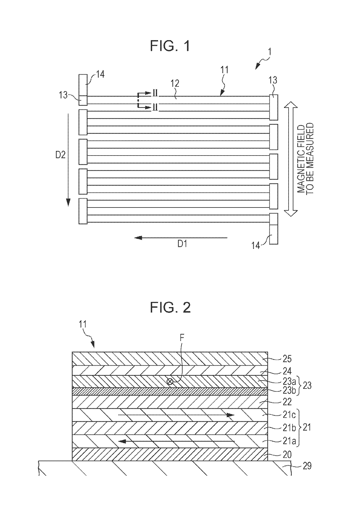
[0079]On a substrate having an insulating film, a seed layer: NiFeCr (42) / fixed magnetic layer [first magnetic layer: Co40Fe60 (19) / nonmagnetic interlayer: Ru (3.6) / second magnetic layer: Co90Fe10 (24)] / nonmagnetic material layer: Cu (20) / free magnetic layer {second ferromagnetic layer: [Co90Fe10 (10) / Ni81.5Fe18.5 (10)] / magnetic adjustment layer: (Ni81.5Fe18.5)100-xPtx (Y) / first ferromagnetic layer: Ni81.5Fe18.5 (10)} / first antiferromagnetic layer: Ir22Mn78 (60) / protective layer: Ta (100) were sequentially laminated to each other from the bottom, so that a laminate structural body was obtained. The numerical value in the parentheses indicates the layer thickness, and the unit thereof is Å.

[0080]In addition, Y (thickness of the magnetic adjustment layer) was set so that when×(content of Pt in the magnetic adjustment layer) was changed, the magnetization amount (Ms·t) of the magnetic adjustment layer was equivalent to the magnetization amount (Ms·t) of the reference layer. In particul...

example 1

Measurement Example 1

Measurement of Reduction Rate RMs of Saturation Magnetization Ms

[0082]The saturation magnetizations Ms (unit: T) at 25° C. and 150° C. of the reference layer of Comparative Example 1 and the saturation magnetizations Ms at 25° C. and 150° C. of the magnetic adjustment layer of each of Examples 1 to 4 were measured. From the data thus obtained, the reduction rate RMs of the saturation magnetization Ms was obtained. In addition, the Curie temperatures of the materials forming the reference layer and each magnetic adjustment layer were measured. The results are shown in Table 2.

TABLE 2Curie temper-Ms atMs at ature25° C.150° C.RMsTca(T)(T)(%)(° C.)Comparative1.091.026.46580Example 1Example 10.780.5529.4372Example 20.620.3248.3275Example 30.450.1273.0162Example 40.240.0010045

[0083]As shown in Table 2, in the magnetic adjustment layers according to Examples, the reduction rate RMs of the saturation magnetization Ms was more than 10%. FIG. 5 is a graph showing the rela...

example 2

Measurement Example 2

Measurement of Exchange Coupling Bias Hex

[0084]The exchange coupling bias Hex (unit: Oe) of each of the relative laminate structural body of Comparative Example 1 and the laminate structural bodies of Examples 1 to 4 was measured by changing an environmental temperature. The results are shown in Table 3. In addition, based on the results shown in Table 3, the relative value of the exchange coupling bias Hex obtained by normalization using the result at 25° C. is shown in Table 4, and the result obtained by plotting the data shown in Table 4 is shown in FIG. 8.

TABLE 325° C.85° C.150° C.200° C.Comparative 42.1036.3020.9110.20Example 1Example 139.8036.0723.5013.66Example 240.0438.7231.1017.28Example 341.3741.7539.9821.18Example 441.810.000.000.00

TABLE 425° C.85° C.150° C.200° C.Comparative 10.860.500.24Example 1Example 110.910.590.34Example 210.970.780.43Example 311.010.970.51Example 410.000.000.00

[0085]As shown in Tables 3 and 4 and FIG. 8, it was confirmed that t...


PUM

PropertyMeasurementUnit
temperatureaaaaaaaaaa

Abstract

A magnetic sensor includes a magnetoresistive effect element having a sensitivity axis in a specific direction. The magnetoresistive effect element has on a substrate, a laminate structure in which a fixed magnetic layer and a free magnetic layer are laminated with a nonmagnetic material layer interposed therebetween and includes at a side of the free magnetic layer apart from the nonmagnetic material layer, a first antiferromagnetic layer which generates an exchange coupling bias with the free magnetic layer and aligns a magnetization direction thereof in a predetermined direction in a magnetization changeable state. The free magnetic layer includes a first ferromagnetic layer in contact with the first antiferromagnetic layer to be exchange-coupled therewith and a magnetic adjustment layer at a side of the first ferromagnetic layer apart from the first antiferromagnetic layer. The magnetic adjustment layer contains at least one iron group element and at least one platinum group element.

Description

CLAIM OF PRIORITY[0001]This application claims benefit of Japanese Patent Application No. 2016-124570 filed on Jun. 23, 2016, which is hereby incorporated by reference.BACKGROUND OF THE INVENTION1. Field of the Invention[0002]The present invention relates to a magnetic sensor and a current sensor including the magnetic sensor.2. Description of the Related Art[0003]In motor drive-technique fields for electric cars and hybrid cars, infrastructure-related fields, such as pole transformers, and the like, since a relatively large current is used, a current sensor capable of measuring a large current in a contactless manner has been required. As the current sensor described above, a current sensor using a magnetic sensor detecting an induced magnetic field from a current to be measured has been known. As a magnetic detection element for the magnetic sensor, for example, a magnetoresistive effect element, such as a giant magnetoresistive effect (GMR) element, may be mentioned.[0004]A GMR e...

Claims


Application Information

Patent Timeline
Patent Type & Authority Applications(United States)
IPC IPC(8): G01R33/09G01R33/31G01R15/20G01R33/00H01F1/00H01F1/153
CPCG01R33/091G01R15/205H01F1/153G01R33/0082H01F1/0009G01R33/31H01F10/3268H01F10/3272
Inventor IDE, YOSUKE
Owner ALPS ALPINE CO LTD
Why Eureka
Try Eureka