Semiconductor device
a technology of semiconductor devices and solders, applied in semiconductor devices, semiconductor/solid-state device details, control systems, etc., can solve the problems of reducing and achieve the effect of increasing the reliability of the connection the reliability of the second solder
- Summary
- Abstract
- Description
- Claims
- Application Information
AI Technical Summary
Benefits of technology
Problems solved by technology
Method used
Image
Examples
first embodiment
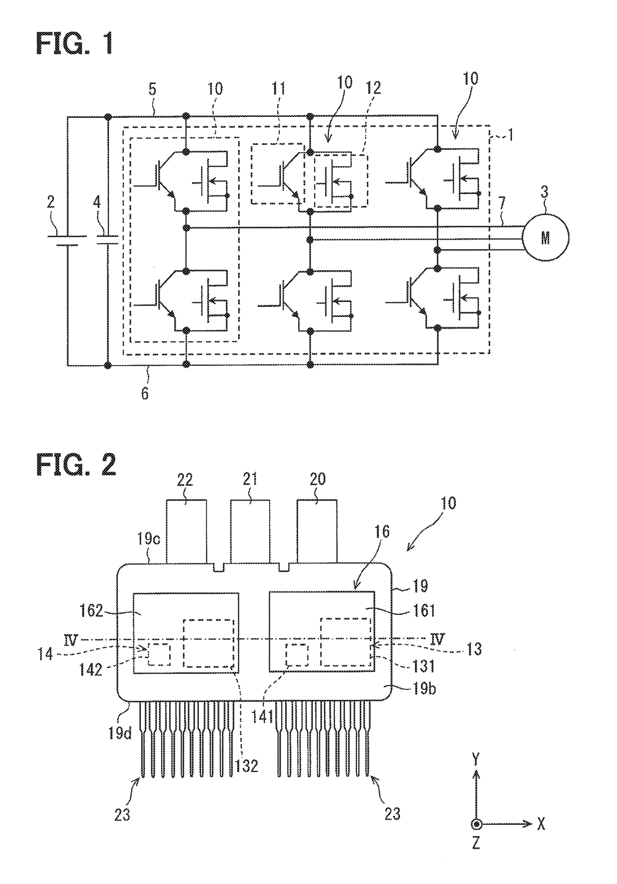
[0033]An example of an electrical power conversion device in which a semiconductor device is employed will be described with reference to FIG. 1.
[0034]An electrical power conversion device 1 shown in FIG. 1 converts a direct current (DC) voltage supplied from a DC power source 2 into a three-phase alternating current (AC), and outputs the three-phase AC to a motor 3 that is a three-phase AC motor. The electrical power conversion device 1 is mounted to, for example, an electrical vehicle or a hybrid vehicle. The electrical power conversion device 1 may convert an electrical power generated by the motor 3 into a DC power and may charge the DC power source 2 (e.g., a battery). Therefore, the motor 3 may be referred to as a motor generator. An element designated by a symbol 4 in FIG. 1 is a smooth capacitor 4.
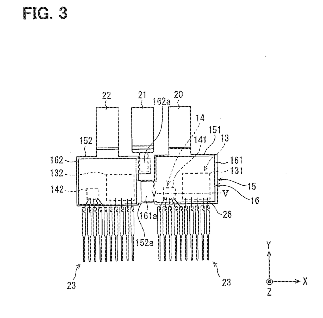
[0035]The electrical power conversion device 1 has a three-phase inverter. The three-phase inverter includes three phases of upper and lower arms disposed between a high-potential ...
second embodiment
[0096]In a second embodiment, portions that are common to the semiconductor device 10 described in the first embodiment will not be repeatedly described.
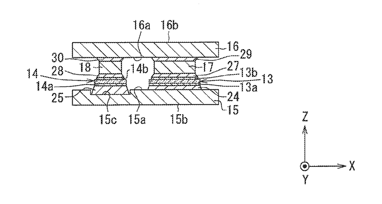
[0097]As shown in FIG. 7, in the second embodiment, the thickness of the solder 25 is greater than the maximum thickness of the first solder 24 at an entire periphery of the outer peripheral edge of the drain electrode 14a. Specifically, as shown in FIG. 8, the recess 15c is annularly formed to include the entire periphery of the outer peripheral edge of the drain electrode 14a, that is, the second semiconductor chip 14. In FIG. 8, an inner peripheral edge of the recess 15c is shown by a broken line. Similarly to FIG. 6, the illustration of the solder 25 is omitted in FIG. 8.
[0098]In the second embodiment, similar effects to the first embodiment are achieved. Especially in the second embodiment, the thickness of the solder 25 is increased at the entire periphery of the outer peripheral edge of the drain electrode 14a, to which the t...
third embodiment
[0100]In a third embodiment, portions that are common to the semiconductor device 10 described in the first embodiment will not be repeatedly described.
[0101]In the third embodiment, the thickness of the solder 25 is greater than the maximum thickness of the first solder 24 at corners (i.e., angles) of the drain electrode 14a having almost planar rectangular shape. The drain electrode 14a is formed in almost the entire surface of the second semiconductor chip 14 facing the heat sink 15. The corners of the drain electrode 14a are almost coincident with the corners of the second semiconductor chip 14. Therefore, the thickness of the solder 25 is greater than the maximum thickness of the first solder 24 at the corners 14c of the second semiconductor chip 14 having almost planar rectangular shape.
[0102]Specifically, as shown in FIG. 9, the recesses 15c are respectively formed to correspond to four corners 14c of the second semiconductor chip 14. Each of the recesses 15c is integrally fo...
PUM
 Abstract
Description
Claims
Application Information
 - R&D
- Intellectual Property
- Life Sciences
- Materials
- Tech Scout
- Unparalleled Data Quality
- Higher Quality Content
- 60% Fewer Hallucinations
Browse by: Latest US Patents, China's latest patents, Technical Efficacy Thesaurus, Application Domain, Technology Topic, Popular Technical Reports.
© 2025 PatSnap. All rights reserved.Legal|Privacy policy|Modern Slavery Act Transparency Statement|Sitemap|About US| Contact US: help@patsnap.com


