
Friction material

a technology of friction material and friction material, which is applied in the field of friction material, can solve the problems of inability to reliably operate with conventional friction materials in wet clutch applications, lack of requisite cof and durability, and inconsistent cof of friction materials with smaller pore sizes, so as to increase the average pore size of the porous friction generating layer, improve performance properties, and increase lubricant flow

Active Publication Date: 2018-01-18
BORGWARNER INC
View PDF3 Cites 8 Cited by
  • Summary
  • Abstract
  • Description
  • Claims
  • Application Information

AI Technical Summary

Benefits of technology

The patent describes a new design for a friction material used in wet clutch applications. The design has increased lubricant flow through the material, which improves its performance. This is achieved by increasing the size of pores in the material that are in contact with friction adjusting particles.

Problems solved by technology

Conventional friction materials generally do not function reliably in such wet clutch applications, especially the more recent clutch applications such as wet start clutch applications and shifting applications, e.g. semi-automatic DCT applications.
Although friction materials having improved coefficient of friction (“COF”) have been developed in an attempt to meet the demands of these wet clutch applications, many of the friction materials developed lack the requisite COF and durability due in large part to conventional friction materials having pores which are too small.
Friction materials having smaller pore size tend to provide an inconsistent COF over a range of conditions.
Further, friction materials having smaller pore size tend to restrict the flow of lubricant through the friction material, this reduced flow causes inadequate cooling, which impacts the performance properties and durability of the friction generating material.
As such, the friction materials developed for these wet clutch applications contribute to a variety of complications including lack of sufficient torque transfer, shuddering, shift shock, and poor durability.

Method used


Image

  • Friction material
  • Friction material
  • Friction material

Examples


first embodiment

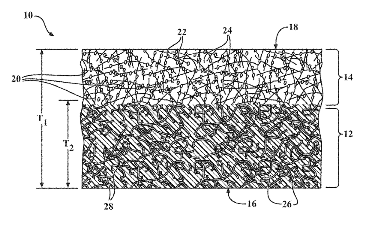
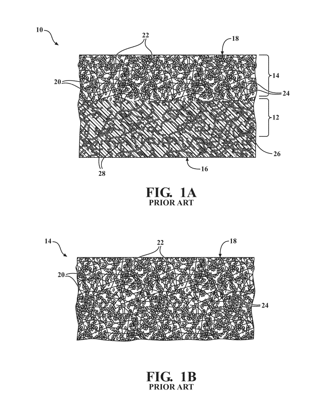
[0072]A method of forming the porous friction generating material 10 is also disclosed herein. In a first embodiment, the method includes the steps of (1) impregnating a base paper with the curable resin 26, (2) dispersing the fibers 20 and the friction adjusting particles 22 onto the base paper, and (3) curing the porous friction generating material 10.

second embodiment

[0073]In a second embodiment, the method includes the steps of (1) mixing the friction adjusting particles 22 and the curable resin 26 to form resin 26 coated particles 22, (2) mixing the resin 26 coated particles 22 and the fibers 20 to bond the friction adjusting particles 22 to the fibers 20 such that the fibers 20 are in contact with the friction adjusting particles 22, (3) dispersing the fibers 20 which are in contact with the friction adjusting particles 22 onto the base paper, and (4) curing the porous friction generating material 10. Of course, embodiments where the fibers 20 and the resin 26 coated particles 22 are dispersed onto the base paper in two distinct steps are also contemplated herein.

third embodiment

[0074]In a third embodiment, the method includes the steps of (1) mixing the fibers 20 and the curable resin 26 to form resin 26 coated fibers 20, (2) mixing the resin 26 coated fibers 20 and the friction adjusting particles 22 to bind the friction adjusting particles 22 to the resin 26 coated fibers 20 such that the fibers 20 are in contact with the friction adjusting particles 22, (3) dispersing the fibers 20 which are in contact with the friction adjusting particles 22 onto the base paper, and (4) curing the porous friction generating material 10. Of course, embodiments where the resin 26 coated fibers 20, and the friction adjusting particles 22 are dispersed onto the base paper in two distinct steps are also contemplated herein.


PUM

PropertyMeasurementUnit
pore sizeaaaaaaaaaa
densityaaaaaaaaaa
average diameteraaaaaaaaaa

Abstract

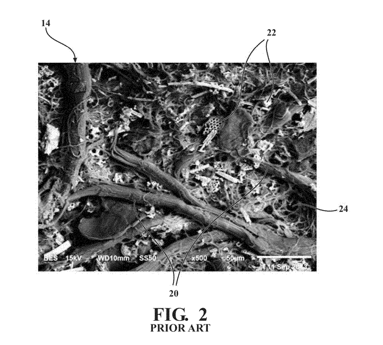
A friction material comprises a base and a porous friction generating layer penetrating into and integral with the base. The base presents a bonding surface. The porous friction generating layer presents a friction generating surface facing opposite the bonding surface of the base. The porous friction generating layer comprises fibers and friction adjusting particles, and about 30 to about 95% of a total surface area of the fibers is in contact with the friction adjusting particles. A curable resin is dispersed throughout the porous friction generating layer and the base.

Description

CROSS-REFERENCE TO RELATED APPLICATIONS[0001]This application claims priority to and all the advantages of U.S. Provisional Patent Application No. 62 / 362,906, filed on Jul. 15, 2016, the content of which is incorporated herein by reference.FIELD OF THE DISCLOSURE[0002]The subject disclosure generally relates to a friction material comprising a base and an indiscreet friction generating layer. More specifically, the subject disclosure relates to a friction material which can be used in a friction plate in a clutch assembly in a transmission.DESCRIPTION OF THE RELATED ART[0003]Several components of a motor vehicle powertrain may employ a wet clutch to facilitate the transfer of power from the vehicle's power generator (i.e. an internal combustion engine, electric motor, fuel cell, etc.) to the drive wheels. A transmission which is located downstream from the power generator and which enables vehicle launch, gear shifting, and other torque transfer events is one such component. Some fo...

Claims


Application Information

Patent Timeline
Patent Type & Authority Applications(United States)
IPC IPC(8): F16D69/02F16D13/74F16D69/00
CPCF16D69/028F16D13/74F16D2069/005F16D2200/0069F16D2069/002F16D2200/0065F16D69/026F16D2069/007F16D13/60F16D69/02F16D69/023
Inventor DONG, FENGLIU, WANJUN
Owner BORGWARNER INC
Learn More