Ultrasonic imaging device, method for adjusting inter-transmission weight,and ultrasonic imaging method

a technology of ultrasonic imaging and inter-transmission weight, which is applied in the field of ultrasonic imaging technique, can solve problems such as difficulty in enhancing azimuth resolution, and achieve the effect of reducing the spatial variation of the amplification factor of phasing signals with respect to each receive phasing point and achieving high-quality images

Active Publication Date: 2018-01-25
FUJIFILM HEALTHCARE CORP
View PDF0 Cites 4 Cited by
  • Summary
  • Abstract
  • Description
  • Claims
  • Application Information

AI Technical Summary

Benefits of technology

[0011]According to the present invention, in the aperture synthesis, spatial variation of the amplification factor of the phasing signals with respect to each receive phasing point is reduced, allowing a high quality image to be obtained.

Problems solved by technology

Since transmit / receive aperture size is limited, the ends of the element group to be used are influenced by diffraction of the ultrasonic waves, and thus it is difficult to enhance azimuth resolution.

Method used


Image

  • Ultrasonic imaging device, method for adjusting inter-transmission weight,and ultrasonic imaging method
  • Ultrasonic imaging device, method for adjusting inter-transmission weight,and ultrasonic imaging method
  • Ultrasonic imaging device, method for adjusting inter-transmission weight,and ultrasonic imaging method

Examples


first embodiment

[0032]A first embodiment of the present invention will be described with reference to the accompanying drawings. Hereinafter, in all the figures illustrating the embodiment of the present invention, components with an identical function are labeled with the same reference numeral, and they will not be redundantly explained.

[Ultrasound Imaging Apparatus]

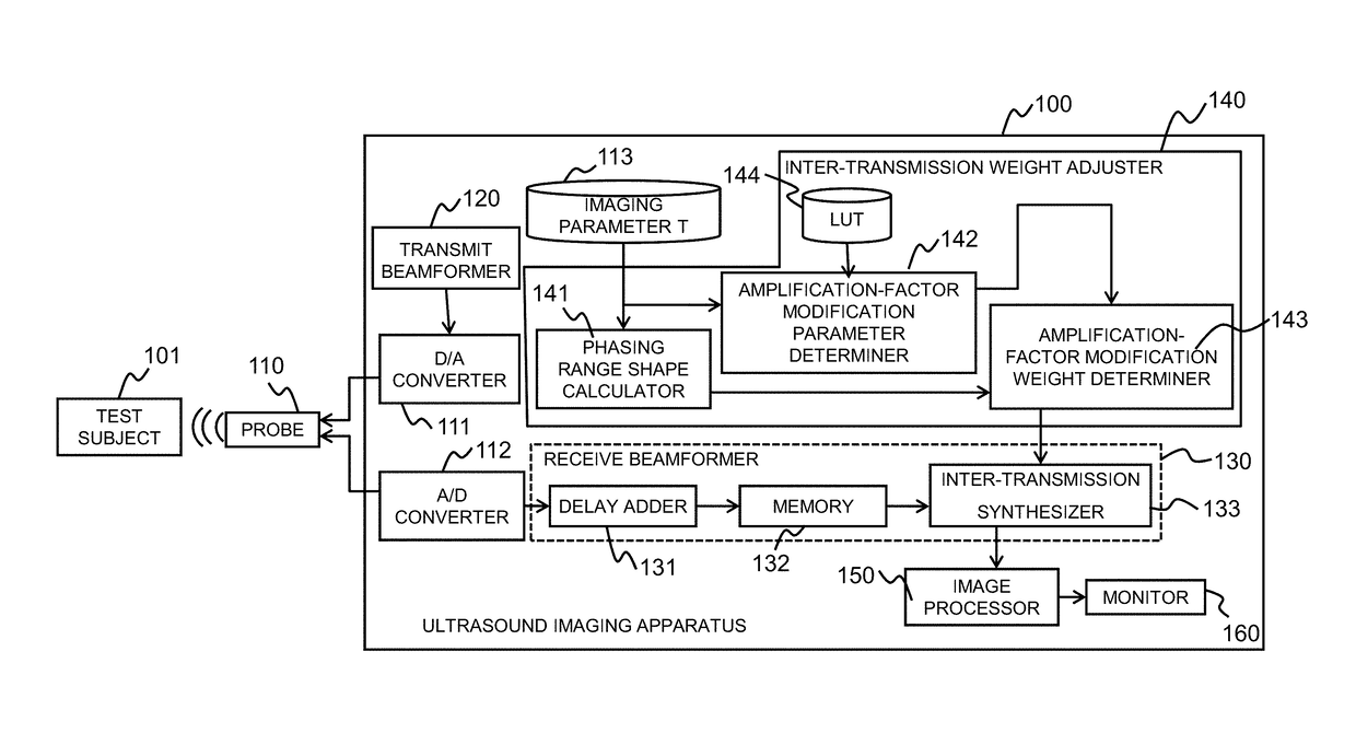
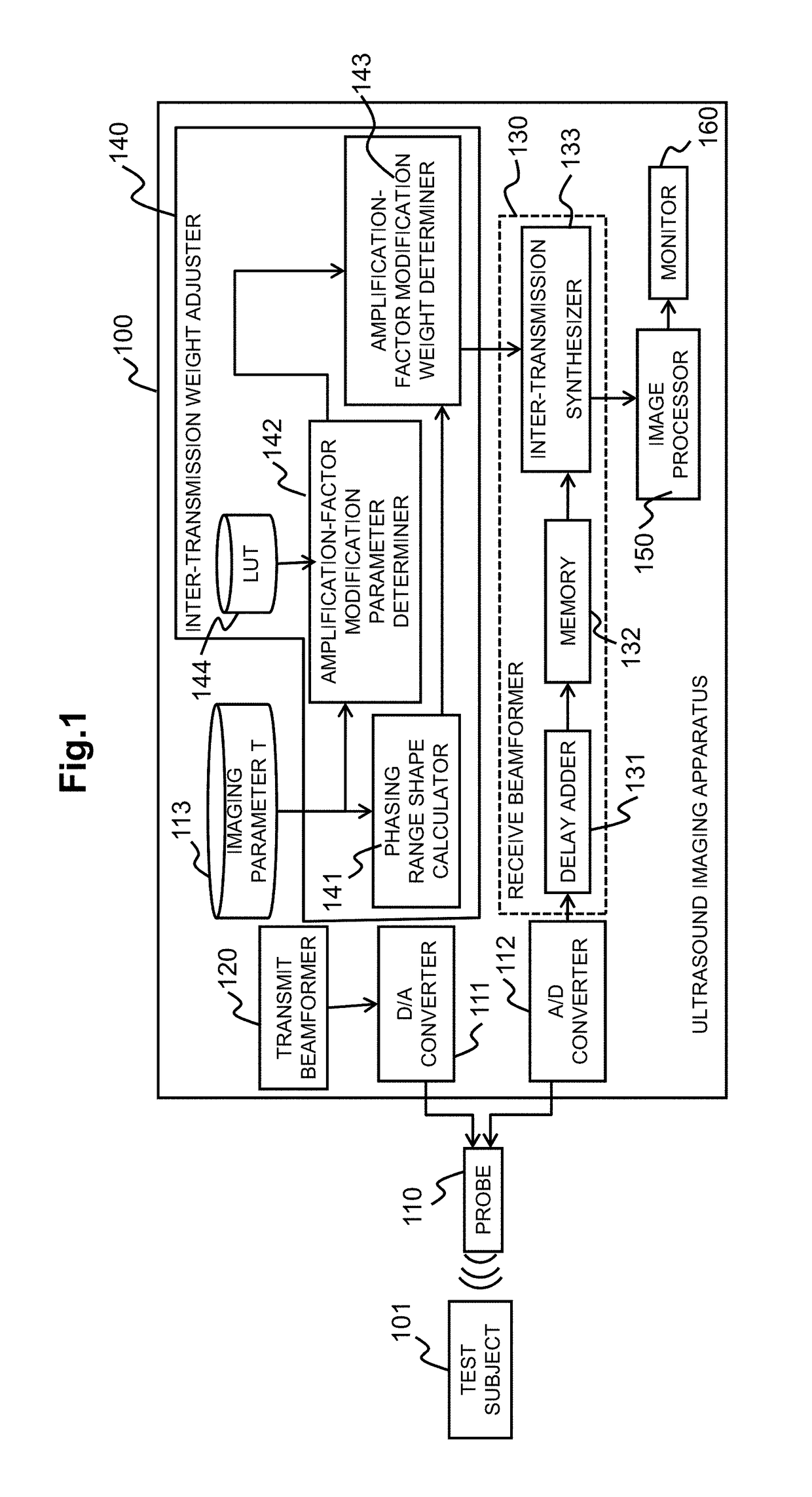
[0033]An ultrasound imaging apparatus of the present embodiment will now be described. FIG. 1 is a block diagram showing a configuration of the ultrasound imaging apparatus according to the present embodiment. As illustrated, the ultrasound imaging apparatus 100 of the present embodiment is provided with a probe 110, a transmit beamformer 120, a receive beamformer 130, inter-transmission weight adjuster 140, an image processor 150, a monitor 160, a D / A converter 111, an A / D converter 112, and an imaging parameter table (imaging parameter T) 113.

[0034]The probe 110 comprises an array of plural ultrasound elements along a predetermined ...

second embodiment

[0115]Next, the second embodiment of the present invention will be described. In the first embodiment, for adjusting the inter-transmission weight, the weight adjustment parameter (inclined strength) is acquired from the LUT that is prepared in advance. On the other hand, in the present embodiment, instead of preparing the LUT, and an appropriate weight adjustment parameter is determined according to a search.

[0116]FIG. 15 is a functional block diagram showing the ultrasound imaging apparatus 100a of the present embodiment. As illustrated, the ultrasound imaging apparatus 100a of the present embodiment has basically the same configuration as the first embodiment. However, since a method of determining the weight adjustment parameter is different, the inter-transmission weight adjuster 140 is not provided with the LUT 144. Instead, the inter-transmission weight adjuster 140 is provided with a verification unit 145 configured to verify suitability of the inter-transmission weight that...

third embodiment

[0139]A third embodiment of the present invention will now be described. In the present embodiment, the image is displayed, which is obtained from the result of the aperture synthesis by using the adjusted inter-transmission weight, and further adjustment of the weight adjustment parameter is accepted from a user.

[0140]An initial inter-transmission weight may be calculated according to any of the following methods, the method of the first embodiment or the method of the second embodiment. Alternatively, the method may be determined in advance. In the following, the case where calculation is made according to the method of the first embodiment will be described by way of example.

[0141]The ultrasound imaging apparatus 100b of the present embodiment has basically the same configuration as the ultrasound imaging apparatus 100 of the first embodiment. In addition, in order to accept the adjustment from the user (operator) as described above, it is further provided with a configuration fo...


PUM


Abstract

In performing aperture synthesis according to an ultrasound imaging apparatus, the amount of spatial change of amplification factors of phasing signals at respective receive phasing points are reduced, and a high-quality image is obtained. In a receive beamformer that generates an inter-transmission weight in accordance with a phasing range, and performs aperture synthesis processing, the inter-transmission weight being generated is applied to the receive phasing points within the phasing range obtained through transmission and reception, and the inter-transmission synthesis is performed. The inter-transmission weight is generated in such a manner that a variation form of the amplification factor between adjacent receive phasing points is smoothed and a difference of the amplification factor is reduced, as to each receive phasing point after the inter-transmission synthesis is performed.

Description

TECHNICAL FIELD[0001]The present invention relates to an ultrasound imaging technique for taking an internal image of a test subject by using ultrasonic waves. In particular, the present invention relates to aperture synthesis techniques for synthesizing phasing signals obtained through multiple transmissions, so as to generate an image from results of the synthesis.BACKGROUND ART[0002]Medical image display units, notably ultrasound imaging, MRI, and X-ray CT imaging, are widely used as devices for presenting in vivo data incapable of visual check, in the form of numerical values or picture images. In particular, an ultrasound imaging apparatus that is an image display unit using ultrasonic waves, is provided with a higher time resolution relative to other devices, and accordingly it is possible to create an image of pulsating heart without halation, for instance.[0003]The ultrasound imaging apparatus transmits ultrasonic waves into the test subject, receives reflected waves generat...

Claims


Application Information

Patent Timeline
Patent Type & Authority Applications(United States)
IPC IPC(8): A61B8/14A61B8/00
CPCA61B8/14A61B8/4488A61B8/54G01S15/8997G01S7/52033G01S15/8915
Inventor SUZUKI, MAYUMIIKEDA, TEIICHIROMASUZAWA, HIROSHIISHIHARA, CHIZUE
Owner FUJIFILM HEALTHCARE CORP
Why Eureka
Try Eureka