Medical injection device

Active Publication Date: 2018-01-25
JIAXING SUMMED MEDTECH CO LTD
View PDF3 Cites 5 Cited by
  • Summary
  • Abstract
  • Description
  • Claims
  • Application Information

AI Technical Summary

Benefits of technology

[0056]compared with the prior art, the medical injection device of the present utility model has the advantages of simple stru

Problems solved by technology

In this drug delivery device, there are many structural parts, and the components have highly required machining precision and great assembly difficulty.
Moreover, when in use, the internal components easily get stuck or are easily worn out, so that it is likely to result in the failure of the injection device.
In this injecti

Method used


Image

  • Medical injection device
  • Medical injection device
  • Medical injection device

Examples


embodiment 1

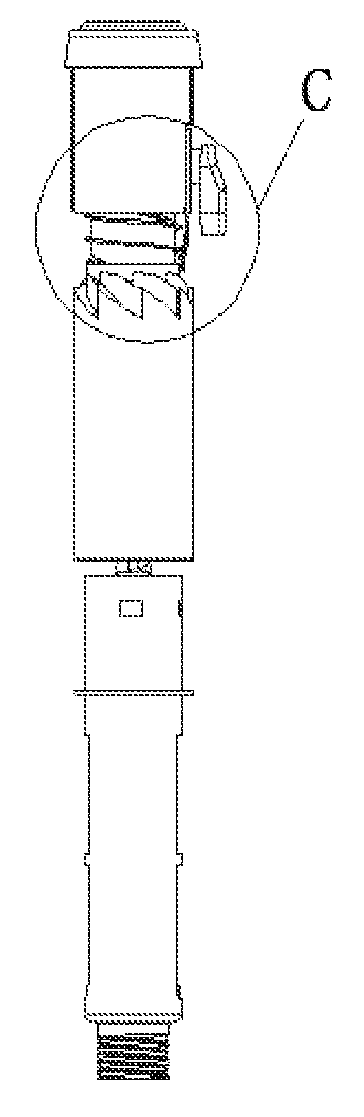
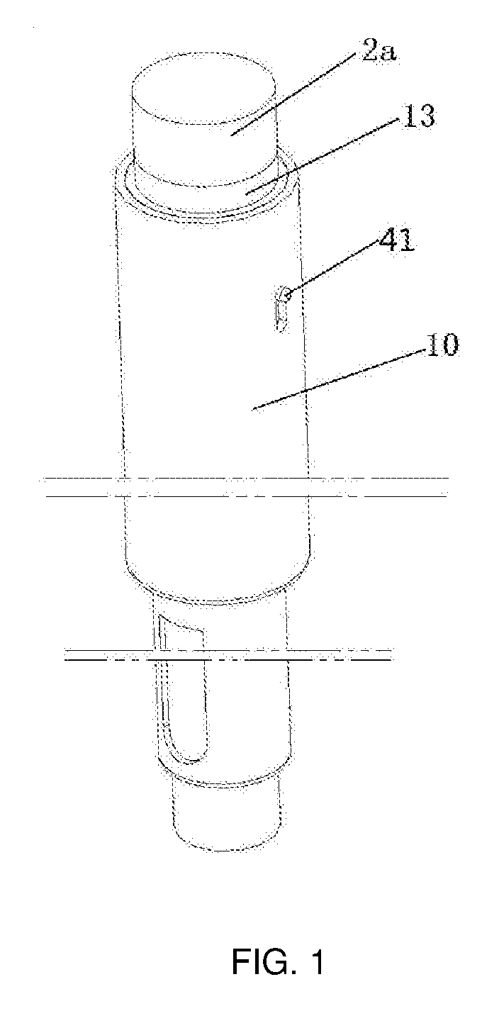
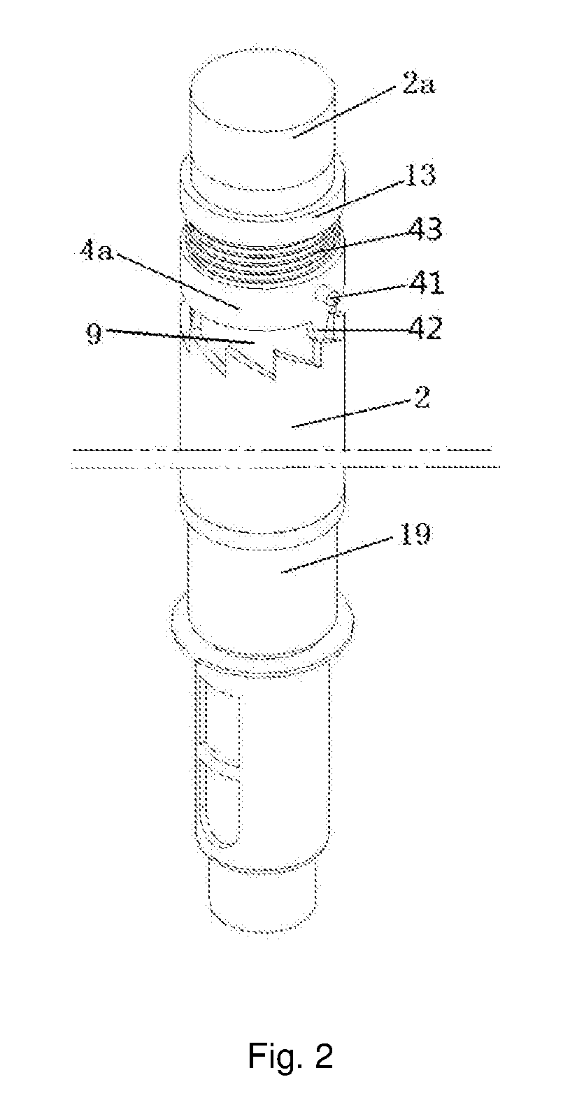
[0085]As shown in FIGS. 1 to 7, Embodiment 1 of the present utility model provides a medical injection device with an adjustable dosage, including a housing 10, a vial which is provided at one end of an inner cavity of a through hole of the housing 10 and has a piston 34, a trigger switch button 2a, a piston rod 21, a dial threaded rod 9, a dosage adjustment mechanism arranged within the housing 10, and a driving mechanism, wherein a first end cover 13 is provided at an upper end of the housing 10, while a second end cover 19 is provided a lower end thereof; the second end cover 12 is snapped at a lower end of a cavity of a through hole of the housing 10; and, through holes are formed in both the middle of the first end cover 13 and the middle of the second end cover 19. The vial is fixed at a lower end of the housing 10 through a vial sleeve, and an upper end of the vial sleeve is snapped into the second end cover 19. The dose dosage adjustment mechanism includes an adjustment key ...

embodiment 2

[0093]As shown FIGS. 8 to 19, Embodiment 1 of the present utility model provides another medical injection device. This medical injection device mainly consists of a housing 10, a dial threaded rod 9 provided within the housing 10 and having a cavity, a first end cover 13 and a second end cover 19 respectively provided at an upper end and a lower end of the housing 10, a piston rod 21 used for expelling medicine liquid, a first sleeve 20 sheathed on the piston rod 21 and used for driving the piston rod to rotate, a driving member arranged within the cavity of the dial threaded rod 9 and used for driving the first sleeve 20 to rotate, and an elastic pressing member arranged above the second end cover 19 and resisted against the driving member.

[0094]Wherein, preferably, to satisfy the design and assembly requirements in practical applications, optimize processes and save the cost, as shown in FIGS. 12 and 14, the second end cover 19 and the housing 10 are formed integrally, and an end...

embodiment 3

[0132]As shown in FIGS. 20 to 27, Embodiment 3 of the present utility model further provides a medical injection device. The medical injection device in this embodiment is a further improvement based on Embodiment 1 or Embodiment 2, and has the following differences from Embodiment 1 and Embodiment 2: in this embodiment, a protection mechanism for limiting the rotation of the ratchet 2 is provided on the housing 10; the protection mechanism includes a safety switch 8a and a locking mechanism, wherein the locking mechanism is locking teeth arranged on a circumferential surface of the ratchet 2; wherein the safety switch 8a is rotatably arranged within a mounting hole on a side wall of the housing 10, so that a latch 81 of the safety switch 8a is engaged with or disengaged from the locking teeth after the safety switch 8a is rotated. In practical productions and applications, the safety switch 8a is snapped to the mounting hole on the side wall of the housing 10 through a hasp.

[0133]S...


PUM


Abstract

A medical injection device, comprising: a housing having a first end cover and a second end cover provided at two ends thereof, respectively; a dial threaded rod, which is in threaded connected to the first end cover; and, a piston rod, which is used for expelling a dose, an upper end of the piston rod being connected to the dial threaded rod through a driving mechanism while a lower end thereof is in threaded connected to the second end cover. It further comprises a dosage adjustment mechanism, which is arranged between the dial threaded rod and the housing and used for driving the dial threaded rod to move in an axial direction of the housing.

Description

[0001]This application claims priority to Chinese Patent Application Ser. No. CN2016207732715, CN2016207734744, CN2017205472563 and CN2017206064311 filed 21 Jul. 2016, 21 Jul. 2016, 17 May 2017 and 27 May 2017, respectively.TECHNICAL FIELD OF THE UTILITY MODEL[0002]The present utility model relates to the technical field of medical instruments, and particularly relates to a medical injection device with an adjustable dosage.BACKGROUND OF THE UTILITY MODEL[0003]As one common medical instrument, an automatic injection device can accurately expel a desired dosage without manual needle insertion, injection and the like.[0004]Patent No. WO2004 / 078239A1 has disclosed a drug delivery device. The drug delivery device includes: a housing having an internal thread, a dosage dial sleeve having a thread engaged with the internal thread of the housing, a rotary sleeve releasably connected to the dose dial sleeve, and a clutch means located between the dose dial sleeve and the rotary sleeve, wher...

Claims


Application Information

Patent Timeline
IPC IPC(8): A61M5/315A61M5/24A61M5/32
CPCA61M5/31586A61M5/3204A61M5/3257A61M5/31551A61M2205/0216A61M5/2422A61M2005/3126A61M2005/2492A61M5/31541A61M5/24
Inventor WENG, JIAN-SEN
Owner JIAXING SUMMED MEDTECH CO LTD
Why Eureka
Try Eureka