Tidal current energy generating device

a technology of current energy generation and current current, which is applied in the direction of sliding contact bearings, mechanical equipment, machines/engines, etc., can solve the problems of low efficiency, no general-purpose and proven devices are available, and energy needs to be low-carbon, so as to reduce maintenance and installation costs greatly, effectively protect bearings, and reduce power generation efficiency

Inactive Publication Date: 2018-01-25
ZHEJIANG ZHOUSHAN LHD ENERGY DEV
View PDF0 Cites 3 Cited by
  • Summary
  • Abstract
  • Description
  • Claims
  • Application Information

AI Technical Summary

Benefits of technology

[0020]To sum up, the tidal current energy generating device in the invention can allow the generating device to be modularly assembled and replaced above the water surface by disposing separable inner frames and the outer frame, such that the costs of maintenance and installation can be greatly reduced, thereby overcoming the difficulties that the conventional ocean energy generating device cannot be commercialized and large-scale. Further, by disposing at least two hydro turbines and at least three bearings on the center shaft, the “multipoint restriction” is achieved for the center shaft, which makes the scale of the tidal current energy generating device can be extended not only in the horizontal direction (the horizontal direction perpendicular to the water flow) but also in the vertical direction (the depth direction perpendicular to the horizontal plane), such that the power generation efficiency is greatly improved and the problem that the existing ocean energy generating devices cannot “be large” and “be deep” is solved.
[0021]In addition, the underwater shaft rotating protecting device provided by the invention can effectively protect the bearings from the outer impurities, especially preventing the sediments in the water from entering into the bearings, so as to effectively protect the normal operation of the bearings. By adopting the underwater shaft rotating protecting device, the tidal current energy generating device in the invention extends the service lives of the bearings, the maintenance frequency and maintenance costs are greatly reduced, and the power generating efficiency is ensured not to be affected at the same time. Furthermore, the bearing of the tidal current energy generating device provided by the invention can be a rolling bearing, which overcomes the technical barrier that only sliding bearing with water as the lubricant can be used for an underwater shafting in the prior art.
[0022]Moreover, by setting the detection module, whether the sealing of the bearings is reduced or not can be known intuitively and timely, which effectively guides the maintenance personnel when and where to maintain, thereby improving the promptness and reliability of the maintenance. In addition, since the frame includes separable outer frame and inner frame, the underwater shaft rotating protecting device can be maintained or replaced conveniently and quickly, and the maintenance cost is greatly reduced.

Problems solved by technology

Nowadays, with the increasing shortage of energy and the increasing serious green house effect, energy is required to be low-carbon.
No general-purpose and proven devices are available.
The efficiency is relatively low, and it is difficult to realize large-scale devices.
Since the ocean environment is complicated and the water resistance is large, the installation of the conventional ocean energy power generator in the ocean has great difficulties and needs large costs.
In addition, since the power generator contacts the sea water over a long period of time, under long corrosion and huge impaction of the sea water, the ocean energy power generator needs regular maintenance or replacement after being used for a period of time.
However, the maintenance and replacement of the conventional ocean energy power generator are also carried out in the ocean, and thus the difficulty is high and the cost is huge.
Even the whole ocean energy power generator will be scraped only due to the damage of some components, which is one important reason causing the high cost of the ocean energy power generator and is also a direct reason causing the conventional ocean energy power generator failing to realize large-scale and commercialized operation.
However, those skilled in the ocean energy power generating field have overlooked the improvement of the modes of installing and repairing.
In addition, the conventional ocean energy power generator generally only includes one or two vertical-axis hydraulic generators.
However, limited by the manufacturing materials and the environmental conditions, the existing vertical-axis hydro turbine is impossible to be large and deep enough.
The scale of the whole ocean energy power generator is severely limited, the generating power cannot meet the demand, and the cost of power generator is high and cannot be reduced.
However, at present, the technical persons in the ocean energy power generating field have technical bias, only focusing on how to enlarge the impeller of the hydraulic generator or how to improve the structure of blades of the impeller further to improve the generating power of the single hydraulic generator.
At present, no persons in the field research how to improve the generating power and to reduce the costs to facilitate commercialization on the premise that the impeller is not changed.
The reason thereof is not only that the vertical-axis hydro turbine cannot be made long enough in the depth direction as mentioned above, but also that the center shaft of the vertical-axis hydro turbine cannot go deep enough into the ocean.
If the center shaft is made to be very long in prior art, it is likely to be deformed or even broken because of the huge impact force of the sea, and thus the whole generating device cannot be used.
In addition, those skilled in the art have ignored the protection on the center shaft by the bearings.
However, for the generating device utilizing ocean energy, especially tidal current energy, to generate electricity, the center shaft thereof bears a huge impact force exerted by the water flow in the radial direction.
After a period of time, the seal ring between the center shaft and the conventional bearing is easily deformed, and the sealing of the bearing cannot be ensured.
Since the problem of high sealing requirements cannot be solved, the existing ocean energy generating device has to abandon rolling bearings with the oil as a lubricant and can choose sliding bearings which use the water as the lubricant.
In other words, as the water flow usually contains a lot of sediments, if the external water carrying impurities such as sediments flows into the bearing because of the elastic deformation of the sealing rings, not only cannot achieve the lubrication effect to the bearing, but also the normal work of the center shaft is affected, and ultimately the generating efficiency of the generating device is affected.
Therefore, besides the above mentioned problems of installation, maintenance and the length limitation of the center shaft, the conventional ocean energy power generator also usually encounters a problem that the shafting (including the center shaft and the bearing) needs to be replaced, which leads to a higher cost.

Method used


Image

  • Tidal current energy generating device
  • Tidal current energy generating device
  • Tidal current energy generating device

Examples


first embodiment

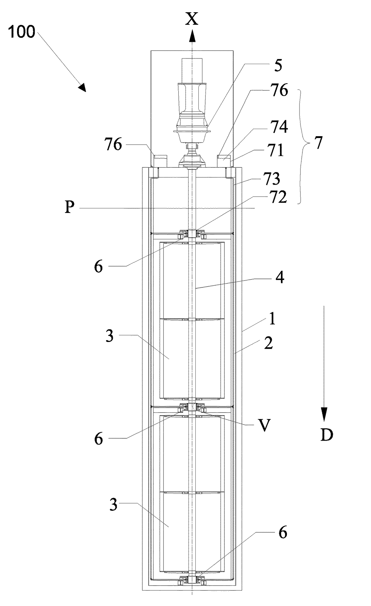
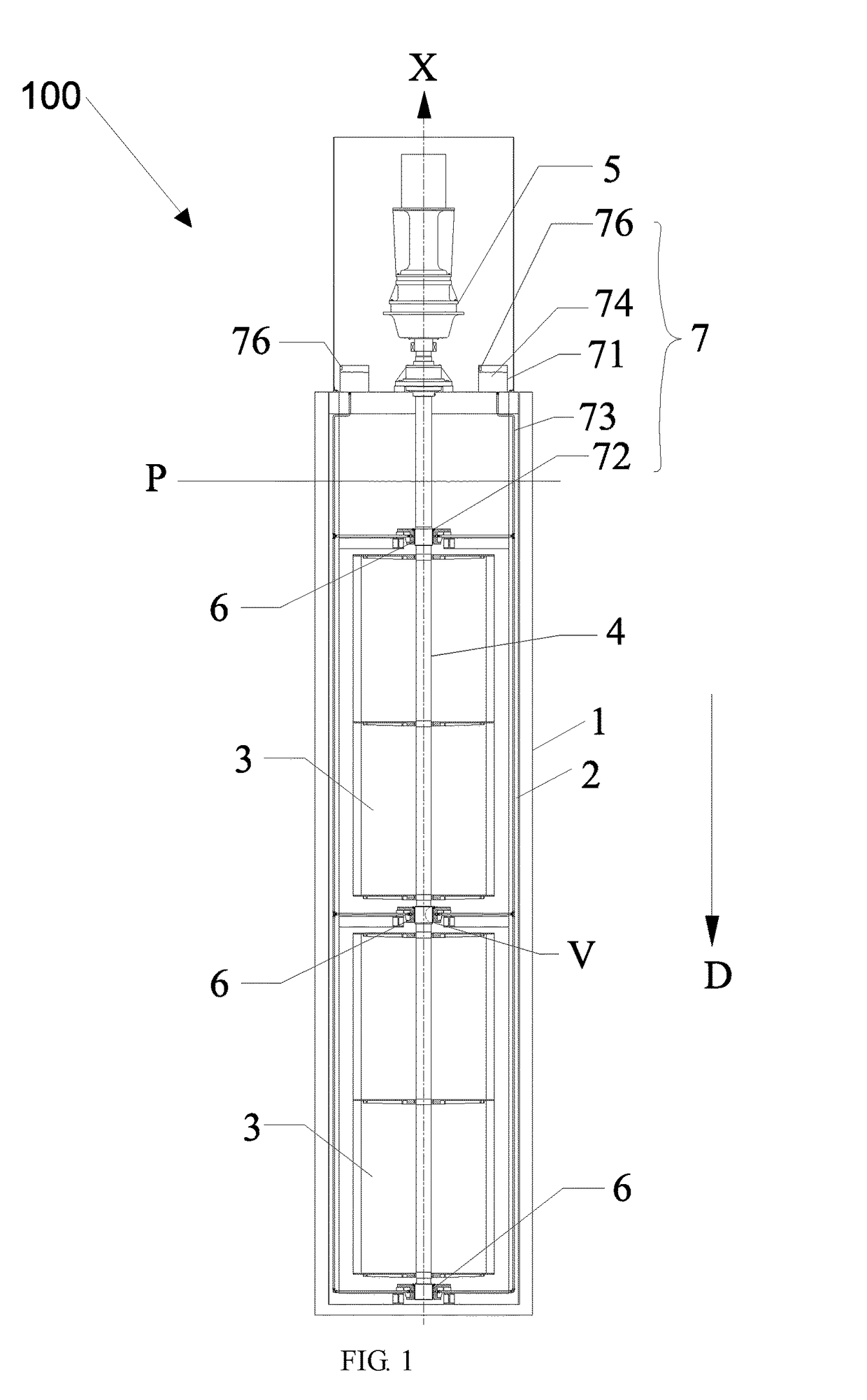
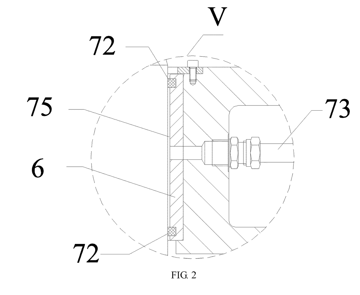
[0030]FIG. 1 is a side view of the tidal current energy generating device provided by the invention. FIG. 2 is an enlarged schematic diagram of circle mark V in FIG. 1. Please refer to FIG. 1 and FIG. 2 together.

[0031]A tidal current energy generating device 100 in the embodiment includes an outer frame 1, at least one inner frame 2, at least two hydro turbines 3, at least one center shaft 4, at least one generator 5, and at least three bearings 6.

[0032]At least one inner frame 2 is separably disposed in the outer frame 1. In the embodiment, a hook may be disposed in the inner frame 2 (not shown in the figure), an engaging slot may be disposed in the outer frame 1 (not shown in the figure), and the inner frame 2 is embedded into the outer frame 1 by the hook and the engaging slot interlocking together. However, the mounting mode of the inner frame 2 and the outer frame 1 in the invention is not limited.

[0033]At least one inner frame 2, at least two hydro turbines 3, at least one cen...

second embodiment

[0061]In the second embodiment, the bearing 6′ includes an inner ring 61′, an outer ring 62′, and a rolling element 63′. The inner ring 61′ is matched with the center shaft 4 and rotates with the center shaft 4, and the outer ring 62′ is matched with a bearing house 76′ as the support. The bearing 6′ changes the sliding friction between the center shaft and the bearing inside the sliding bearing into the rolling friction of rolling elements 63′ between the inner ring 61′ and the outer ring 62′.

[0062]In the embodiment, an underwater shaft rotating protecting device 7′ further comprises three bearing houses 76′, a lubricant cavity 75′ formed by two seal rings 72′, the bearing 6′, the bearing house 76′ and the center shaft 4, and the rolling elements 63′ of the bearing 6′ are located inside the lubricant cavity 75′. Specifically, the bearing house 76′ in the embodiment further includes two end caps 761′. The end cap 761′ can not only have an axial positioning function for the bearing 6...


PUM


Abstract

A tidal current energy generating device includes an outer frame (1), at least one inner frame (2), at least two hydro turbines (3), at least one center shaft (4), at least one generator (5), and at least three bearings (6). The at least one inner frame (2) is separably disposed in the outer frame (1). At least two hydro turbines (3) are located below a water surface and are disposed in one inner frame (2). At least two hydro turbines (3) are disposed coaxially and are vertical-axis hydro turbines. At least one center shaft (4) is disposed through the at least two hydro turbines (3), the axis direction of the center shaft is perpendicular to the horizontal plane, and the center shaft (4) rotates along with the rotating of the hydro turbines (3). The at least one generator (5) is located above the water surface and connected with one end of the center shaft (4). The at least three bearings are sleeved on the center shaft (4) and are located on two sides of and between the two hydro turbines (3), respectively. The tidal current energy generating device can be modularly assembled and replaced above the water surface and can extend along the water depth direction, thereby improving the power generating efficiency.

Description

TECHNOLOGY FIELD[0001]This invention relates to a generating device and, more particularly, to a tidal current energy generating device.BACKGROUND ART[0002]Ocean energy (including tidal energy, tidal current energy, ocean wave energy, and ocean current energy) refers to mechanical energy generated by the flowing of sea water. As a kind of renewable energy, the ocean energy has great development prospect and value due to its abundant reserve and wide distribution. The primary use of the ocean energy is for power generation. The working principle of ocean energy power generation is similar to that of wind power generation and conventional hydropower generation. That is, the mechanical energy of the sea water is converted into electric energy by energy conversion devices. Specifically, at first, the sea water impacts hydro turbines, the hydro turbines convert the energy of the water flow into the mechanical energy of rotation, and then the hydro turbines drive power generators to gener...

Claims


Application Information

Patent Timeline
Patent Type & Authority Applications(United States)
IPC IPC(8): F16C33/10F16N7/02F16C17/12F03B13/26
CPCF16C33/1055F03B13/264F16N7/02F16C17/12F05B2220/32F05B2220/706F05B2240/12F05B2240/50F05B2240/60F16C2380/26F03B3/18F03B11/00F03B11/06F03B13/00F05B2240/57F05B2240/97F05B2250/12F05B2250/141F05B2260/98Y02E10/20F01M11/12F03B13/10H02K7/1823
Inventor LIN, DONG
Owner ZHEJIANG ZHOUSHAN LHD ENERGY DEV
Why Eureka
Try Eureka