System and method for separating carbon dioxide from natural gas

Active Publication Date: 2018-02-01
MITSUBISHI HEAVY IND LTD
View PDF0 Cites 3 Cited by
  • Summary
  • Abstract
  • Description
  • Claims
  • Application Information

AI Technical Summary

Benefits of technology

[0017]The present inventors have found that, when a gas separation membrane is used to separate CO2 from natural gas, H2S and water contained in the natural gas are adsorbed on the separation membrane, thus deteriorating the performance of the separation membrane. Further, since the gas separation membrane removes a significant concentration of CO2 from the natural gas supplied to the gas separation membrane, the partial pressures of components other than CO2 contained in the natural gas rise at the separation membrane. The present inventors et al. have found the following regarding, among these components, water and hydrocarbons with two or more carbon atoms (referred also to as natural gas liquids or NGL) each having a higher boiling point than methane, a main c

Problems solved by technology

Thus, when used, in particular, in processing natural gas with a high concentration of CO2, the me

Method used


Image

  • System and method for separating carbon dioxide from natural gas
  • System and method for separating carbon dioxide from natural gas
  • System and method for separating carbon dioxide from natural gas

Examples


Example

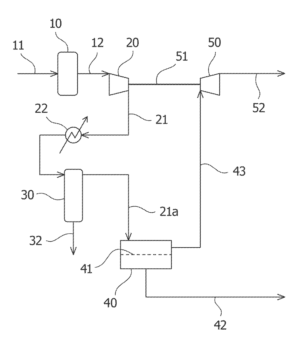
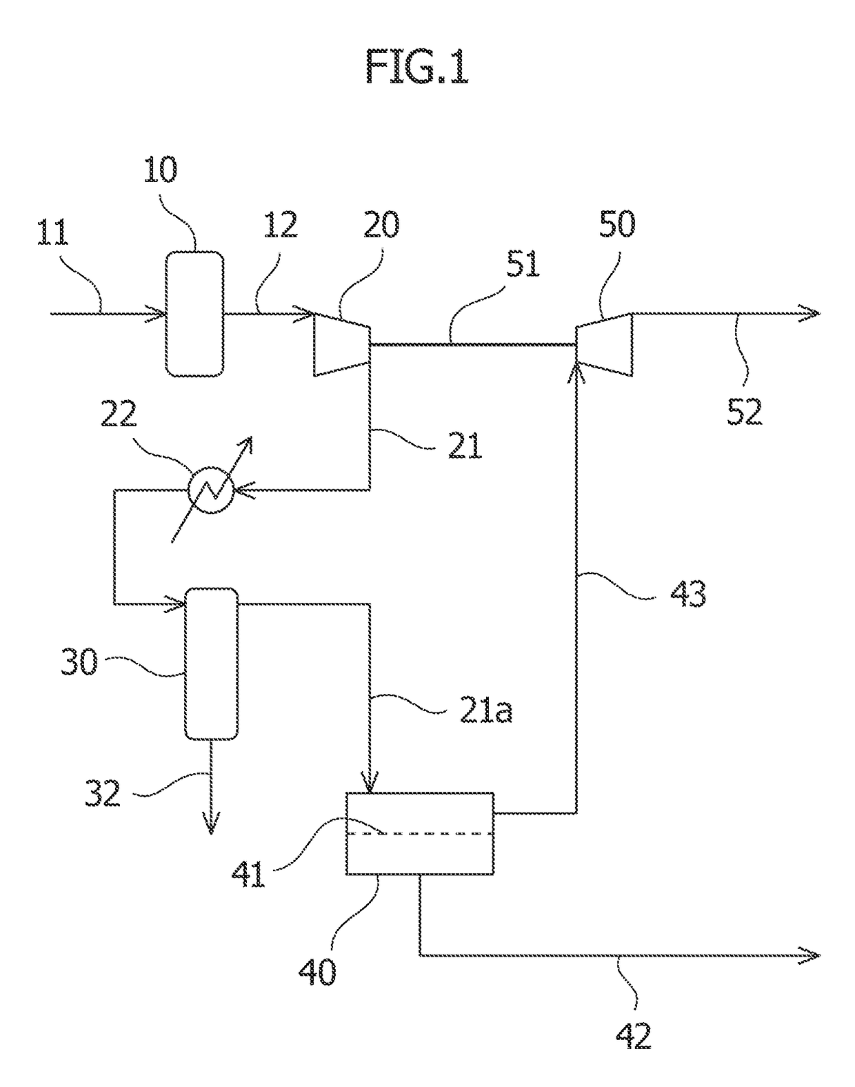
[0022]With reference to the accompanying drawings, embodiments of a system and method for separating CO2 from natural gas according to the present invention will be described below.

[0023]As shown in FIG. 1, a system for separating CO2 from natural gas according to an embodiment mainly includes an H2S remover 10, a compressor 20, a CO2 separator 40, and an expander 50. The H2S remover 10 removes H2S from natural gas that contains CO2 and H2S. The compressor 20 pressurizes the natural gas from which H2S has been removed by the H2S remover. The CO2 separator 40 separates CO2 from the natural gas that has been pressurized by the compressor 20. The expander 50 expands the natural gas from which CO2 has been separated by the CO2 separator, and thereby recovers energy from the natural gas.

[0024]The H2S remover 10 is provided with a raw gas supply line 11 for supplying raw natural gas containing CO2 and H2S to the present system. The H2S remover 10 is not particularly limited, but it is pre...


PUM


Abstract

A system and method for separating CO2 from natural gas, which ensure that no clogging or deterioration occurs in a gas separation membrane even after the gas separation membrane is used to remove carbon dioxide from the natural gas under conditions in which the natural gas is pressurized. First, an H2S remover removes hydrogen sulfide from raw natural gas. Then, a compressor pressurizes the natural gas from which H2S has been removed. After that, a cooler cools the pressurized natural gas so as to condense components that are a part of the natural gas. A gas/liquid separator removes the condensed components, and a CO2 separator, including a separation membrane for separating CO2 removes CO2 from the natural gas from which the condensed components have been removed. An expander, which shares a drive shaft with the compressor, expands the natural gas from which CO2 has been removed and recovers energy therefrom.

Description

TECHNICAL FIELD[0001]The present invention relates to a system and method for separating carbon dioxide (CO2) from natural gas.BACKGROUND ART[0002]Natural gas produced from gas fields or oil fields includes many impurities such as CO2. After such impurities such as CO2 have been removed from the natural gas, the resultant gas is shipped as product gas. In a known CO2 removal method, CO2 is absorbed and removed from the natural gas by use of an amine absorbing liquid as disclosed, for example, in JP 2005-296817 A. This method requires regeneration of the absorbing liquid that has absorbed much CO2 by heating the absorbing liquid to release CO2. Thus, when used, in particular, in processing natural gas with a high concentration of CO2, the method requires a large amount of energy and thus incurs huge operating costs, which is problematic.[0003]In another known CO2 removal method, CO2 is removed using a gas separation membrane with high CO2 selectivity. In this connection, JP 2009-1139...

Claims


Application Information

Patent Timeline
IPC IPC(8): B01D53/22B01D53/04C10L3/10B01D53/26
CPCB01D53/229B01D53/265B01D53/04C10L3/104B01D2253/116B01D2253/106B01D2256/24B01D2257/304B01D2257/504B01D2257/80C10L2290/548C10L2290/06B01D53/26C10L2290/54B01D71/021B01D71/028C10L3/103B01D2253/108B01D2256/245C10L2290/46C10L2290/48Y02C20/40
Inventor TANAKA, YUKIOAKIYAMA, TOMOHYOSHIYAMA, RYUJIEDA, MASAYUKI
Owner MITSUBISHI HEAVY IND LTD
Why Eureka
Try Eureka